Dc bus voltage / memory, Decel time, Dc bus voltage / memory decel time – Rockwell Automation 20B PowerFlex 70, PowerFlex 700 Reference Manual User Manual
Page 69
DC Bus Voltage / Memory
Rockwell Automation Publication PFLEX-RM001H-EN-P - June 2013
69
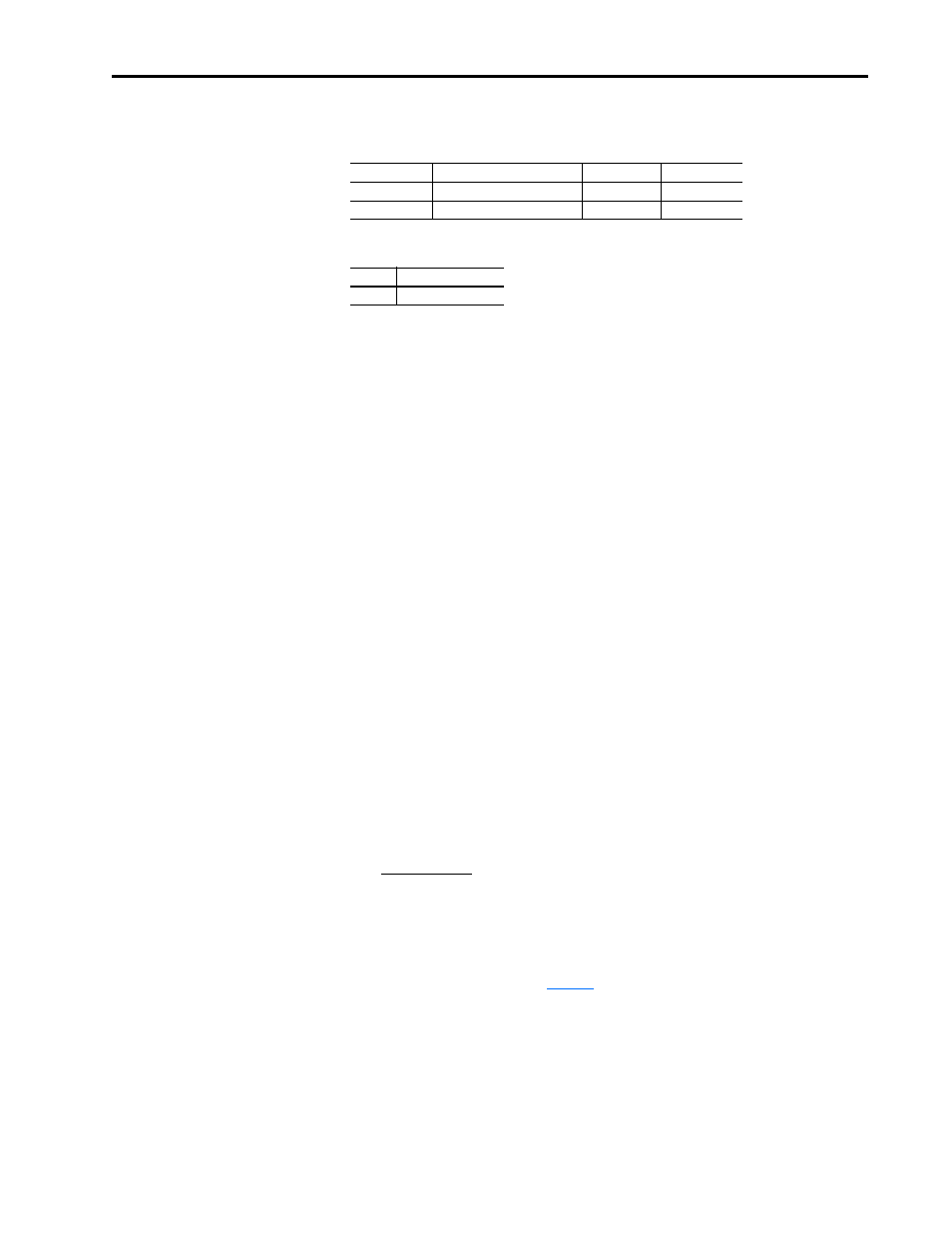
Even if non-consecutive Datalinks are used (in the next example, Datalinks A1
and B2 would not be used), data is still returned in the same way.
32-bit data is stored in binary as follows:
Example
Parameter 242 - [Power Up Marker] = 88.4541 hours
MSW = 13
decimal
= 1101
binary
= 2
16
+ 2
18
+ 2
19
= 851968
LSW = 32573
851968 + 32573 = 884541
DC Bus Voltage / Memory
[DC Bus Voltage] is a measurement of the instantaneous value. [DC Bus
Memory] is a heavily filtered value or “nominal” bus voltage. Just after the
pre-charge relay is closed during initial power-up bus pre-charge, bus memory is
set equal to bus voltage. Thereafter it is updated by ramping at a very slow rate
toward Vbus. The filtered value ramps at approximately 2.4V DC per minute
(for a 480V AC drive).
Bus memory is used as the base line to sense a power loss condition. If the drive
enters a power loss state, the bus memory will also be used for recovery (i.e.
pre-charge control or inertia ride through upon return of the power source) upon
return of the power source. Update of the bus memory is blocked during
deceleration to prevent a false high value caused by a regenerative condition.
Decel Time
[Decel Time 1, 2]
Sets the rate at which the drive ramps down its output frequency after a Stop
command or during a decrease in command frequency (speed change). The rate
established is the result of the programmed Decel Time and the Minimum and
Maximum Frequency, as follows:
Two decel times exist to allow the user to change rates “on the fly” via PLC
command or digital input. The selection is made by programming [Decel Time
1] & [Decel Time 2] and then using one of the digital inputs ([Digital Inx Sel])
programmed as “Decel 2” (see
for further information). However, if a
PLC is used, manipulate the bits of the command word as shown below.
Datalink
Most/Least Significant Word
Parameter
Data (decimal)
A2
MSW
242
13
B1
LSW
242
32573
MSW
2
31
through 2
16
LSW
2
15
through 2
0
Maximum Speed
Decel Time
= Decel Rate (Hz/sec)