Data parameters, Monitor data parameters – Rockwell Automation 1440-VSE02-01RA XM-122 gSE Vibration Module User Manual
Page 99
Publication GMSI10-UM013D-EN-P - May 2010
Configuration Parameters 89
Data Parameters
The Data parameters are used to view the measured values of the input
channels and the 4–20 mA outputs, as well as to monitor the status of the
channels, alarms, and relays.
Monitor Data Parameters
TIP
To view all the data parameters in the XM Serial
Configuration Utility, click the View Data tab.
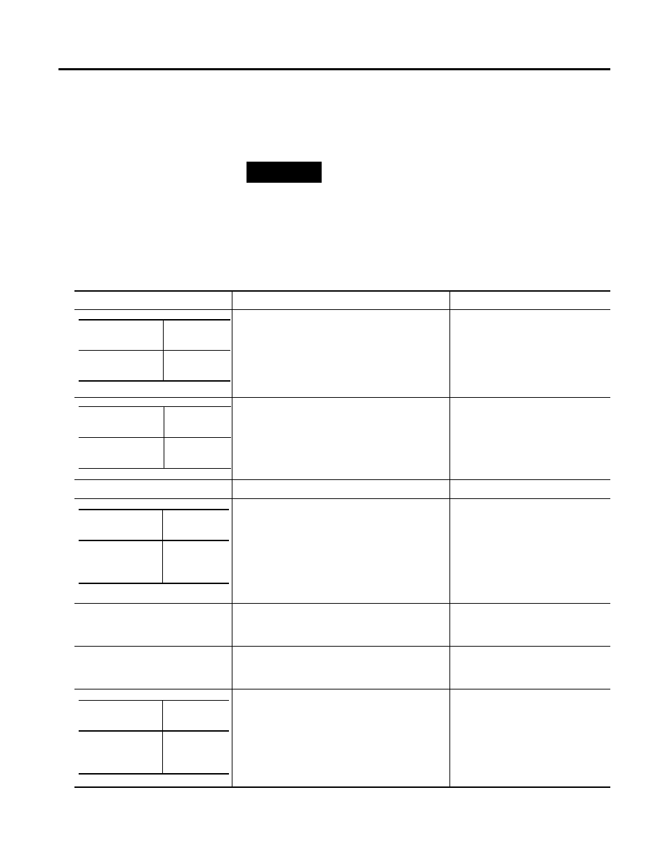
Monitor Data Parameters
Parameter Name
Description
Values/Comments
States whether a transducer fault exists on the
associated channel.
If a fault exists, the overall and gap values may not
be accurate.
Possible status values: No Fault
Fault
Shows the measured average DC offset of the
transducer signal. This value is compared with Fault
High and Fault Low to determine whether the
transducer is working properly.
Gap Value (EDS File only)
Shows the measured transducer gap value.
Shows the measured sum harmonics value.
Sum Harmonics Requirements:
•
The tachometer must be enabled
(Pulses Per Revolution set to 1 or
more), and a tachometer signal must
be present.
•
Sampling Mode must be set to
"Synchronous."
Overall
Shows the measured overall value.
Band Measurement Status (XM
Serial Configuration Utility only)
States whether a fault condition exists on the
associated channel. If a fault exists, the band
measurements may not be accurate.
Possible status values: No Fault
Fault
Shows the measured band value.
XM Configuration
Utility
EDS File
Transducer Fault
Transducer
Status
XM Configuration
Utility
EDS File
DC Gap Voltage
Measured
DC Bias
XM Configuration
Utility
EDS File
Sum Harmonics
Sum
Harmonics
Value
XM Configuration
Utility
EDS File
Band
Measurement
Band
Measured
Value