Connecting the transducer, Connecting an iepe accelerometer – Rockwell Automation 1440-VSE02-01RA XM-122 gSE Vibration Module User Manual
Page 192
Publication GMSI10-UM013D-EN-P - May 2010
182 Wiring Connections for Previous Module Revisions
Connecting the Transducer
The XM-122 can accept input from any Allen-Bradley non-contact eddy
current probe, a standard IEPE accelerometer, or a DC voltage output
measurement device such as a velocity or pressure transducer.
Connecting an IEPE Accelerometer
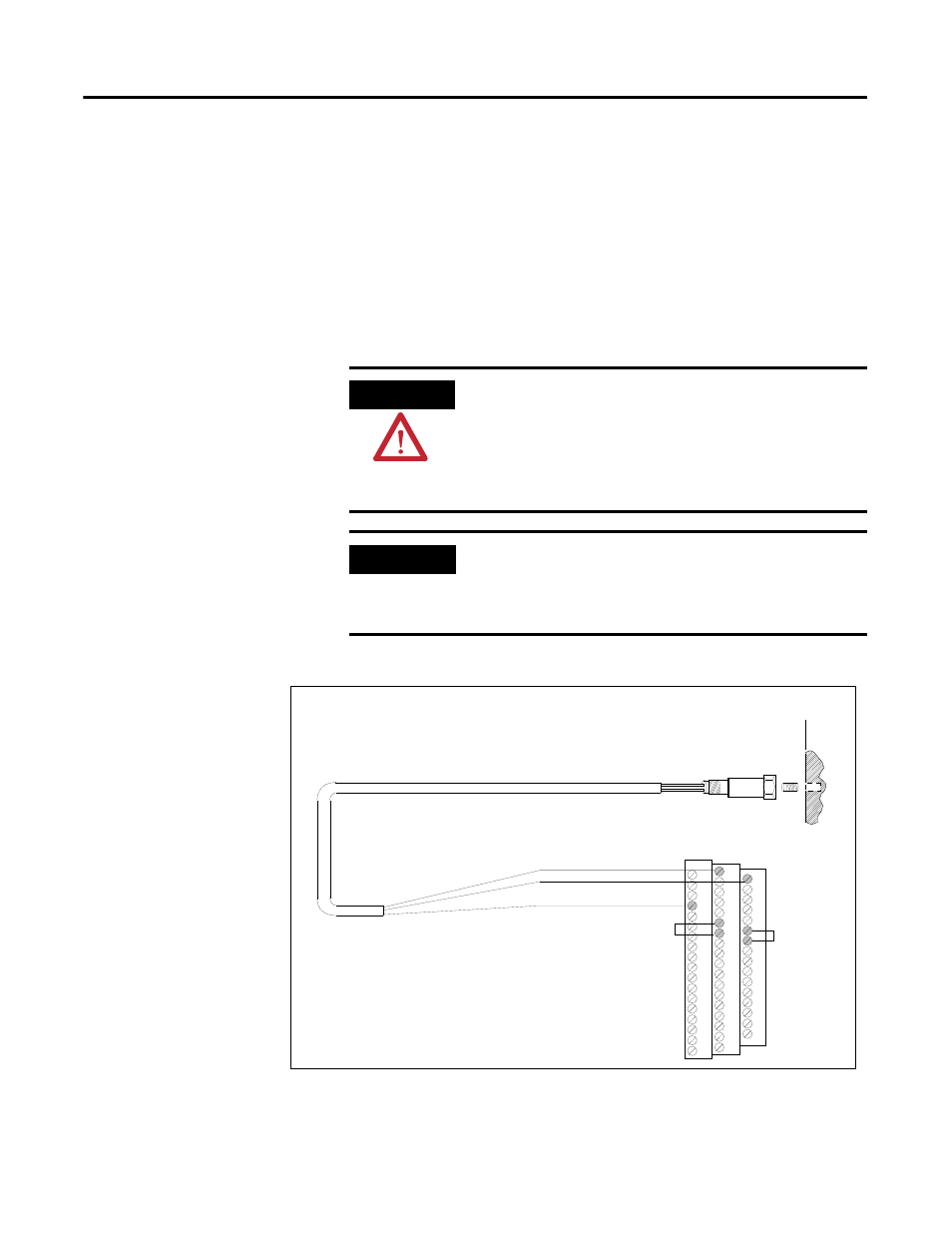
Figures D.2 and D.3 show the wiring of an IEPE accelerometer to an earlier
revision of the XM-122 module (before revision D01).
Figure D.2 IEPE Accelerometer to Channel 1 Wiring
ATTENTION
You may ground the cable shield at either end of the cable.
Do not ground the shield at both ends. Recommended
practice is to ground the cable shield at the terminal base
and not at the transducer. Any convenient Chassis terminal
may be used (see Terminal Block Assignments on page
179).
IMPORTANT
The internal transducer power supply is providing power to
the IEPE accelerometer. Make certain the IEPE Power
parameter is enabled. Refer to Channel Transducer
Parameters on page 58.
TYPICAL WIRING FOR IEPE ACCELEROMETER
TO XM-122 VIBRATION MODULE CHANNEL 1
Shield
Pin A - Signal
Pin B - Common
Cable shield not
connected at this end
0
16
22
6
21
Channel 1 Input Signal
Signal Common
5
37
Jumping terminals
5 to 6 & 21 to 22
configure the
transducer power
supply for IEPE
tranducer(s)