Figure 2.28 sh, Figure 2.28, Important – Rockwell Automation 1440-VSE02-01RA XM-122 gSE Vibration Module User Manual
Page 50: Attention
Publication GMSI10-UM013D-EN-P - May 2010
40 Installing the XM-122 gSE Vibration Module
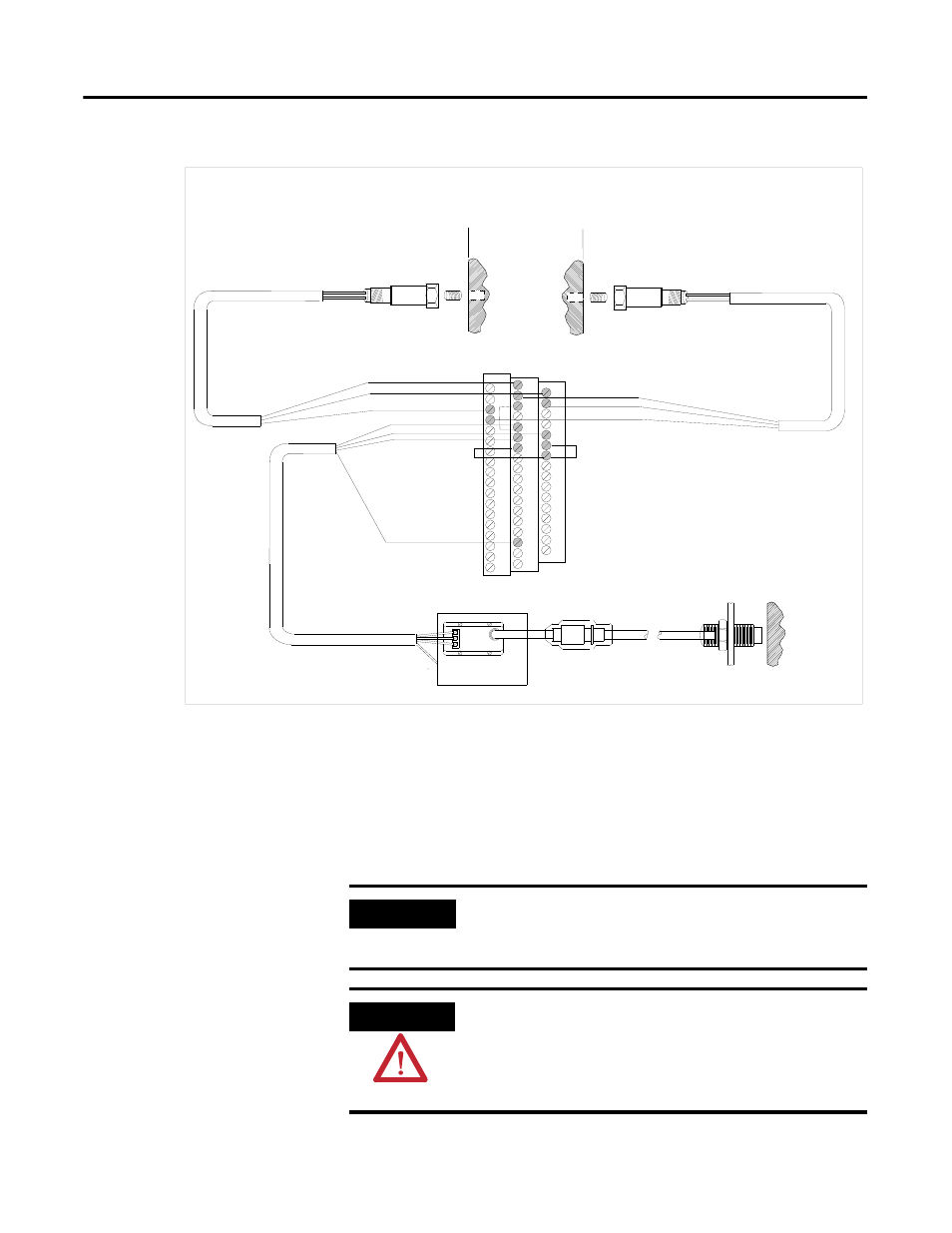
Figure 2.28 Two IEPE Accelerometers and a Non-Contact Sensor Wiring
Connecting a Velocity Sensor and Two Non-Contact Sensors
Figure 2.29 shows the wiring of a velocity sensor and two non-contact sensors
to the terminal base unit. The velocity sensor is wired to channel 1. The first
non-contact sensor is wired to channel 2, and the other non-contact sensor is
wired to the tachometer input signal.
TYPICAL WIRING FOR TWO IEPE ACCELEROMETERS AND
NON-CONTACT SENSOR TO XM-122 VIBRATION MODULE
Shield
Pin A - Signal
Pin B - Common
Cable shield not
connected at this end
0
16
22
6
21
Channel 1 Input Signal
Signal Common
5
37
SIG
-24
COM
17
1
Signal Common
Channel 2 Input Signal
-24V DC
Pin A - Signal
Pin B - Common
Cable shield not
connected at this end
Shield
36
20
4
Tach Input Signal
Signal Common
31
Shield
Shield
Floating
Isolated Sensor Driver
*
*
* Note: Jumpering terminal 5 to terminal 6
configures CH 1 buffer (-5V to +24V)
Jumpering terminal 22 to terminal 6
configures CH 2 buffer (-5V to +24V)
18
IMPORTANT
Figure 2.29 shows the wiring to the XM-122 module
revision D01 (and later). If you have any earlier revision of
the module, refer to Appendix D for wiring information.
ATTENTION
You may ground the cable shield at either end of the cable.
Do not ground the shield at both ends. Recommended
practice is to ground the cable shield at the terminal base
and not at the transducer. Any convenient Chassis terminal
may be used (see Terminal Block Assignments on page 18).