Rockwell Automation 7000 PowerFlex Medium Voltage AC Drive (B Frame) - Classic Control User Manual
Page 472
7-50
Troubleshooting
7000-UM150I-EN-P – June 2013
7000 “B” Frame
WARNING
MESSAGE
WARNING
CODE
DESCRIPTION
RECOMMENDED ACTIONS
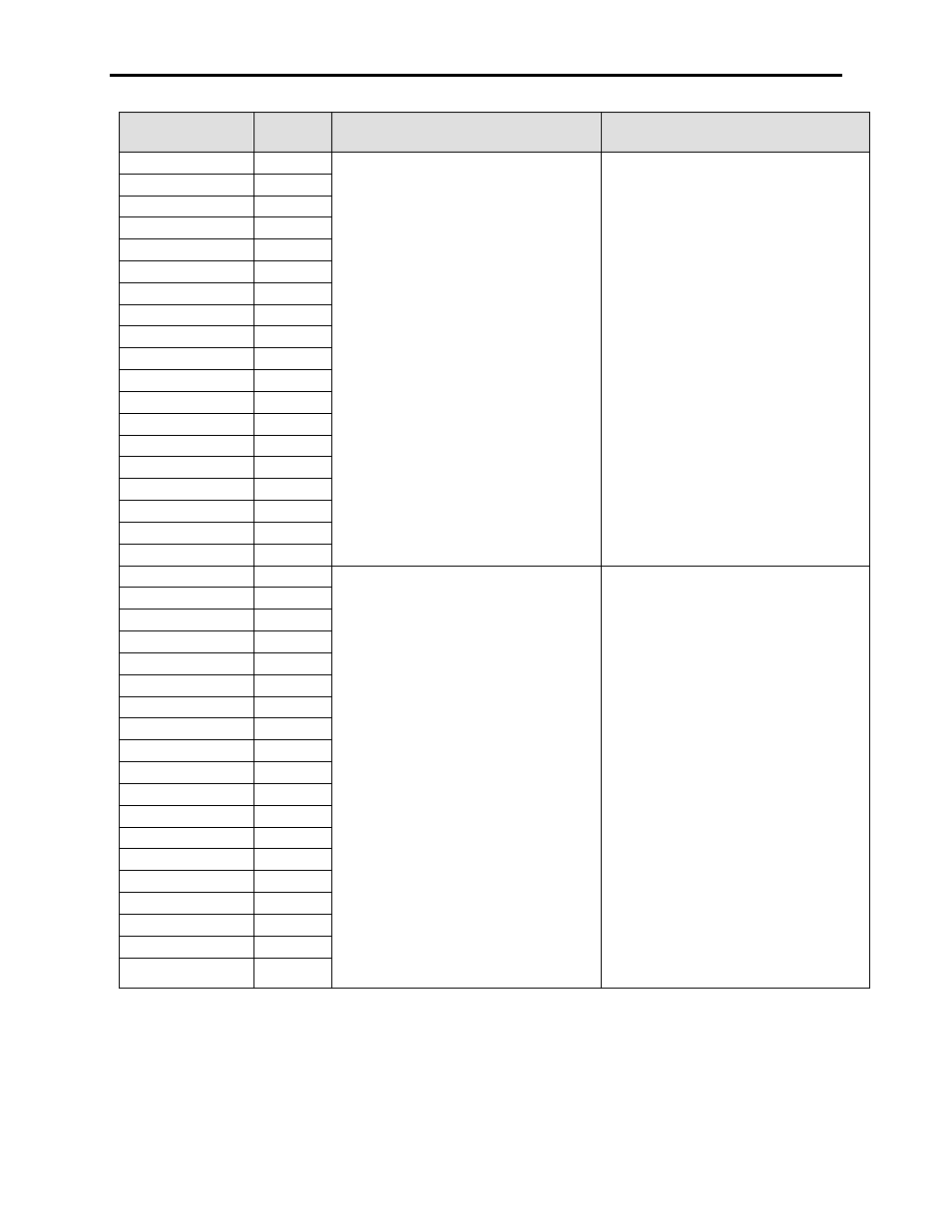
2U1A Offline SC
300
6P SCR RECTIFIER WARNING
(Offline Short-Circuit)
FOR REDUNDANT DEVICE CAPABILITY
ONLY
For SCR rectifiers, this warning will occur
after the initial contact closure, or during the
diagnostic sequence after a start command.
This is the first test on the rectifier. When all
devices blocking, the feedback from the
devices should toggle from open to short to
open every time the line voltage sine wave
passes through zero. If this is consistently
showing short (no feedback), then the drive
assumes that the device is Short-Circuited.
– Complete a resistance check on the
rectifier, including the gate-cathode
resistance, the snubber and sharing
resistors
– Complete a firing check on the rectifier
– Verify the snubber circuitry, and the
sharing resistors
– Verify fiber optic integrity from SCRGD
board transmitter to FOI board receiver
– Replace all faulty components
– NOTE: There is only the Redundant
option available on the Rectifier, and only
on 6P drives (SCR orPWM). You can
not have N-1 operation on the rectifier
since we can not control the line voltage.
2U1B Offline SC
306
2U1C Offline SC
318
2U4A Offline SC
303
2U4B Offline SC
309
2U4C Offline SC
321
2V3A Offline SC
302
2V3B Offline SC
308
2V3C Offline SC
320
2V6A Offline SC
305
2V6B Offline SC
311
2V6C Offline SC
323
2W2A Offline SC
301
2W2B Offline SC
307
2W2C Offline SC
319
2W5A Offline SC
304
2W5B Offline SC
310
2W5C Offline SC
322
2U1A Online SC
288
6P SCR RECTIFIER WARNING
(Online Short-Circuit)
FOR REDUNDANT DEVICE CAPABILITY
ONLY
For SCR rectifiers, this warning will occur
during operation. Before an individual leg is
fired, the drive takes 5 samples of the
voltage across that device. This is because
the notching on the line could cause
individual readings to be low. If they are all
low, the device is assumed to be short-
circuited and a warning occurs. There is
also a parameter called Rectifier Device
Diagnostic Delay (P266), which allows you
to change the number of consecutive firings
to eliminate nuisance warnings. It will still
check 5 times before each firing, but will
now require the condition to exist for the
number of consecutive firings set in the
Diagnostic Delay parameter for a warning to
occur.
– For multiple device faults, the risk of a
line to line short exists, so tests with MV
isolated should be attempted
– Complete a resistance check on the
rectifier, including the gate-cathode
resistance, the snubber and sharing
resistors
– Complete a firing check on the rectifier
– Verify the snubber circuitry, and the
sharing resistors
– Verify fiber optic integrity from SCRGD
board transmitter to FOI board receiver
– Replace all faulty components
– For nuisance faults, contact the factory
about extending the Diagnostic Delay
– NOTE: There is only the Redundant
option available on the Rectifier, and
only on 6P drives (SCR orPWM). You
can not have N-1 operation on the
rectifier since we can not control the line
voltage.
2U1B Online SC
294
2U1C Online SC
312
2U4A Online SC
291
2U4B Online SC
297
2U4C Online SC
315
2V3A Online SC
290
2V3B Online SC
296
2V3C Online SC
314
2V6A Online SC
293
2V6B Online SC
299
2V6C Online SC
317
2W2A Online SC
289
2W2B Online SC
295
2W2C Online SC
313
2W5A Online SC
292
2W5B Online SC
298
2W5C Online SC
316