Rockwell Automation 7000 PowerFlex Medium Voltage AC Drive (B Frame) - Classic Control User Manual
Page 317
Component Definition and Maintenance 6-27
7000 “B” Frame
7000-UM150I-EN-P – June 2013
2. To replace a thermal sensor, refer to page P-2 regarding
electrostatic discharge.
3. The heatsink with the thermal sensor must be removed from the
PowerCage. Remove clamp load (refer to Figure 6.19).
4. Remove the device (SGCT or SCR) that is secured to the heatsink
with the thermal sensor. (Refer to Figure 6.15., 6.16 or 6.17).
5. Disconnect the fiber optic cable to the temperature feedback board.
6. Remove two M8 screws holding the heatsink in place.
7. Remove the heatsink with the temperature feedback board from
the PowerCage.
8. Disconnect the plug that connects the thermal sensor to the
circuit board.
9. Remove the screw that attaches the thermal sensor to the heatsink.
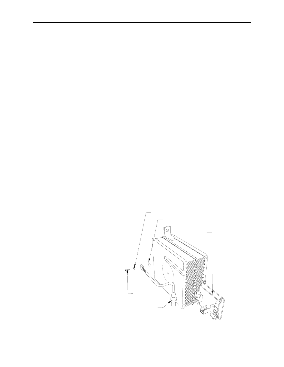
10. Replace with the new thermal sensor and cable assembly.
11. Note there is a small voltage difference between the thermal
sensor and its heatsink. For proper function, it is essential to
mount the small insulating pad between the thermal sensor and
the heatsink and the insulating bushing between the thermal
sensor mounting screw and the thermal sensor (see Figure 6.21).
12. Replacement of the heatsink with the new thermal sensor is in
the reverse order of removal.
13. Follow procedure “Uniform Clamping Pressure” to ensure the
heatsinks are clamped to a uniform pressure.
Insulating bushing
Mounting pad
Temperature
feedback
circuit
board
Thermal sensor and
cable assembly
Mounting screw
Figure 6.21 – Replacing the Heat Sensor