Control power transformer (cpt) – Rockwell Automation 7000 PowerFlex Medium Voltage AC Drive (B Frame) - Classic Control User Manual
Page 201
4-42
Commissioning
7000-UM150I-EN-P – June 2013
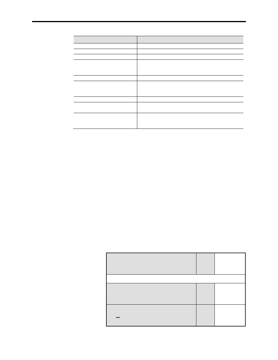
7000 “B” Frame
Component
LED Activated
AC/DC Converter Power Supply
NO Healthy LEDs Provided
DC/DC Converter Power Supply
1 Green LED on Case of Power Supply (No Label)
SGCT Power Supplies
1 Green LED per section of Power Supply (No Label)
SGCT Integrated Firing Card
LED 4 (Green)
LED 3 (Green)
LED 1 (Red)
Drive Control Boards
1 Green LED – Healthy
Customer Interface Board
LED1 (Green)
LED 2 (Green)
LED 3 (Green)
Digital I/O
Various RED Surface Mounted LEDs based on I/O status
Remote I/O Adapter
LED configuration will change based on adapter. Refer to the
adapter user's manual to identify the state the adapter is in.
Operator Interface Terminal
Displays Boot Sequence. Communications Error will occur in
a fault situation. A small flashing indicator in bottom right
corner indicates good communication.
Number of supplies varies based on drive configuration.
Failure of LED to illuminate indicates a problem with the power-up
self-test. See the troubleshooting section of the manual (Chapter 7)
to identify how to troubleshoot the problem.
Control Power Transformer (CPT)
A control power transformer is supplied only in certain drive
configurations. If there is no control transformer supplied in the drive
being commissioned, please disregard the following information on
setting the control voltage output level.
Measure the control voltage level at the secondary of the control
power transformer located in the DC link low voltage cabinet of the
drive. Ensure that the output of the transformer matches the
specification on the electrical schematics.
The value of the output can be adjusted by changing the taps on the
control transformer. Ensure that the power is disconnected at the
Disconnect Switch prior to attempting to change the control
transformer tap setting.
Input Control Voltage (V
L-L
)
U-V:
V-W:
W-U:
________ V
________ V
________ V
Control Power Transformer Installed? Yes
No
CPT Secondary Voltage (V
L-L
)
U-V:
V-W:
W-U:
________ V
________ V
________ V
CPT Secondary Voltage (V
L-N
)
or, if no CPT:
Input Control Voltage (V
L-N
)
U-N:
V-N:
W-N:
________ V
________ V
________ V