Rockwell Automation 7000 PowerFlex Medium Voltage AC Drive (B Frame) - Classic Control User Manual
Page 462
7-40
Troubleshooting
7000-UM150I-EN-P – June 2013
7000 “B” Frame
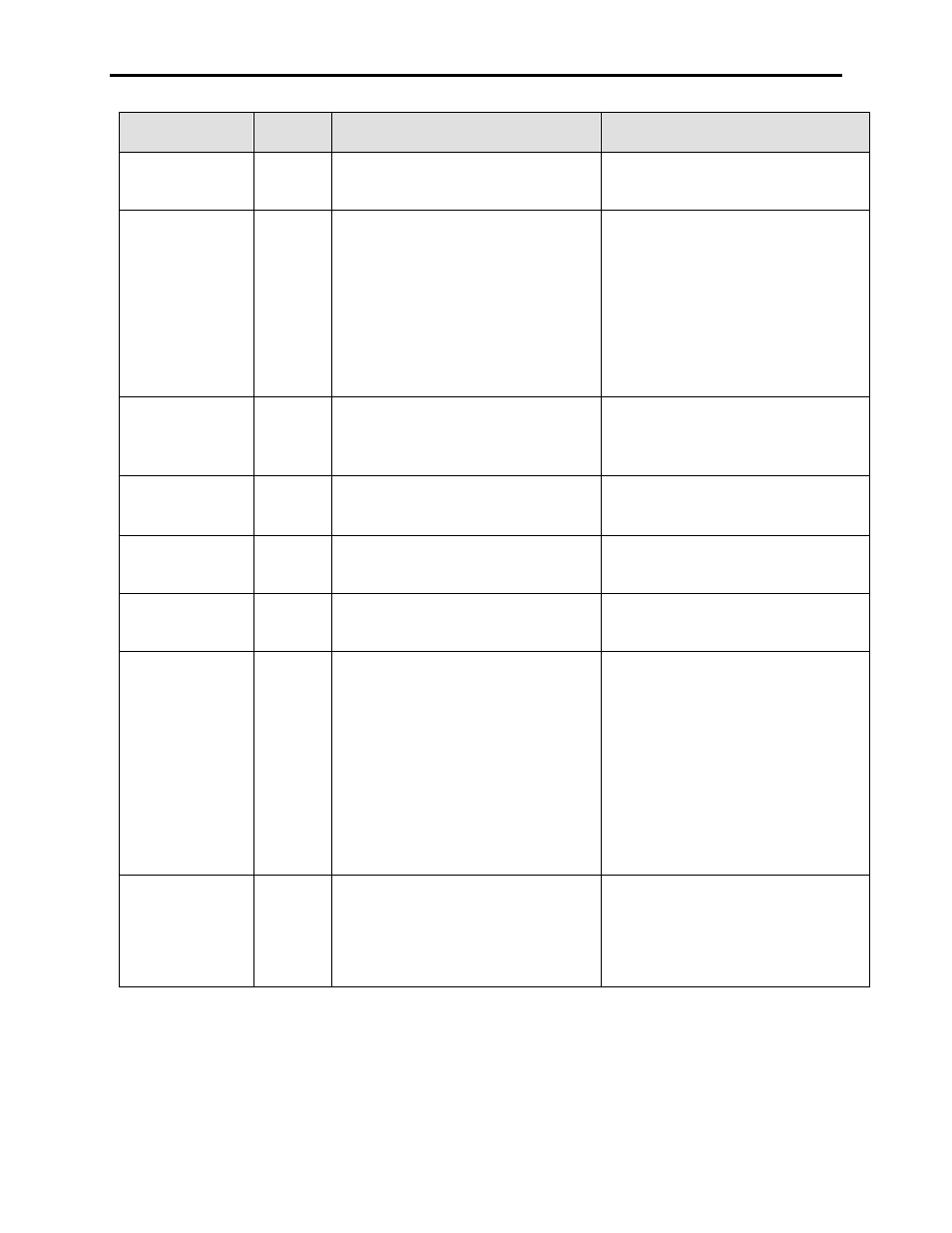
WARNING
MESSAGE
WARNING
CODE
DESCRIPTION
RECOMMENDED ACTIONS
Line DC Link OV
116
The measured Line DC voltage has
exceeded Line DC Overvoltage Trip (P173),
and instantaneously causes a warning.
– See associated Fault Description
Line Loss
120
The drive has detected a loss of input
voltage from losing the frequency (PLL) lock
on the input voltage. This is designed to be
a faster method of detecting an
undervoltage. The drive responds to this
warning as it does to a Master UV warning.
– Verify the VSB connections and tap
settings, and check resistance of VSB
board – Megger board to confirm
integrity
– Check TSN fusing
– Check actual voltage values on the
Terminal for each bridge and the total
line voltage
– Check for possible source voltage
supply problems
Liq IO Config
(C-Frame Only)
131
The XIO card which was being assigned to
the Liquid Cooling System Faults Input is
not a card which can be used for this
purpose
– Select the proper slot containing the XIO
card which is compatible for Liquid
Cooling System Faults usage.
Liq IO Conflict
(C-Frame Only)
132
The XIO card previously being used for
Liquid Cooling System Faults has been
reassigned for another purpose.
– Check the configuration of all XIO slots
and reassign if necessary.
Logx IO Config
133
The XIO card which was being assigned to
Logix IO (basic PLC functionality) is not a
card which can be used for this purpose
– Select the proper slot containing the XIO
card which is compatible for Logix IO
usage.
Logx IO Conflict
134
The XIO card previously being used for
Logix IO (basic PLC functionality) has been
reassigned for another purpose.
– Check the configuration of all XIO slots
and reassign if necessary.
Master UV
112
The measured value V Master Average
(P136) is less than Line Undervoltage Trip
(P167) with respect to 1/3 Rated Line
Voltage (P18) [for 18-pulse drives], and
Rated Line Voltage (P18) [for 6-pulse and
PWM drives] for the period set by Line
Undervoltage Delay (P168).
– Verify the VSB connections and tap
settings, and check resistance of VSB
board – Megger board to confirm
integrity
– Check TSN fusing
– Check actual voltage values on the
Terminal for each bridge and the total
line voltage
– Check for possible source voltage
supply problems
– Use Multimeter and Oscilloscope to
check voltages on the drive test points
Motor Cap Range
23
The calculated per unit value of the Motor
Filter Capacitor (P128), based on the values
entered for Motor Capacitor kVAR (P20),
Motor Capacitor Volts (P21), and Motor
Capacitor Frequency (P28) is outside of the
normal range of 0.26-0.55 pu.
– Verify capacitor nameplate data and
compare with information entered in
drive
– Contact factory