Control power tests, Three phase input – Rockwell Automation 7000 PowerFlex Medium Voltage AC Drive (B Frame) - Classic Control User Manual
Page 199
4-40
Commissioning
7000-UM150I-EN-P – June 2013
7000 “B” Frame
Control Power Tests
Prior to energizing the drive, verify that the control power being
fed into the input breakers are rated as designated on the
electrical diagram.
Although there are a variety of options available to customers
that will effect the control power distribution within the drive,
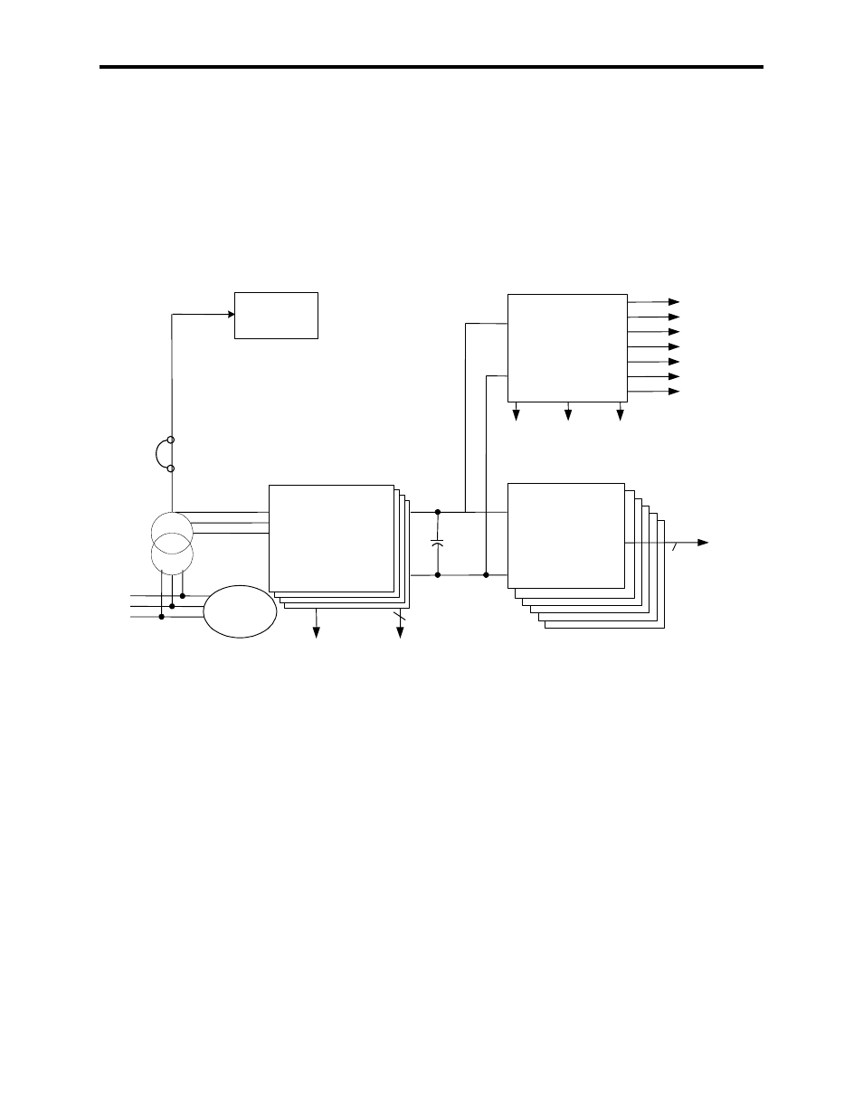
the input will always be as illustrated below:
+24V - PRINT,I/O
Fan
DC/DC
CONVERTER
DC/DC
WARN
SPGDB P/S
FAIL
+5V - LOGIC
+/-15V - LOGIC
+/-24V - LEM
+12V - REM I/O
+15V - TACH
C
hold-up
DC/DC
FAIL
3phase
20V
ISOLATED
GATE DRIVER
POWER SUPPLY
6
20V
PV550 &
Remote I/O
Single
phase
DC
FAIL
AC
FAIL
3 phase
AC/DC
converter
56V
1500W
4
Grounded
neutral
208 V
120 V
CB1
(Optional
CPT)
Figure 4.13 – Control Power Distribution
Three Phase Input
In the 3 phase input configuration, the customer supplies 3 phase
control power into the Fan Disconnect Switch (Labeled FDS1 on the
Electrical Schematics). From that point, the power is distributed to
all the power supplies and controls within the drive. The 3-phase
control should be measured at the input to FDS1. If the rating
matches the designation on the electrical schematic, it is acceptable
to apply control power to the drive. Take necessary measures to
rectify the control power level in the event that it does not meet the
design specifications.