Rockwell Automation 7000 PowerFlex Medium Voltage AC Drive (B Frame) - Classic Control User Manual
Page 230
Commissioning 4-71
7000 “B” Frame
7000-UM150I-EN-P – June 2013
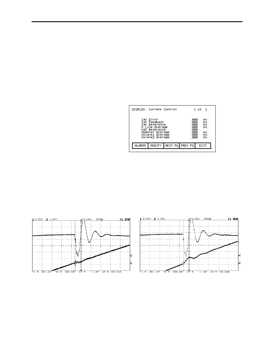
5. Start the drive. The dc link current will rise to 0.4 pu.
Commutation notches will appear in the unfiltered line voltage
VABI-OUT as shown in the figure. Some distortion will appear
in the reconstructed voltage FAB1 around the zero crossings.
6. Measure the average width in degrees of the commutation notch
nearest the peak of the VABI-OUT waveform as seen in the
following figures.
7. Record the values of the parameters "V line average", and "Idc
reference” in “Current control”
8. Calculate the commutation inductance using the following
formula:
L commutation = V line x sin (notch width) / Idc reference
9. Set parameter "L commutation" to the calculated value. If there
was visible distortion in the reconstructed voltage FAB1, the
distortion should decrease. If the distortion increases, it is
possible that the polarity of the line current feedback is
backwards.
COMMUTATION INDUCTANCE TUNED CORRECTLY
COMMUTATION INDUCTANCE INCORRECTLY TUNED
10. Set parameter "Idc command test" to 0.800 pu. The dc current
will increase and the commutation notches will become much
larger.
11. Repeat steps 6 to 9. The higher current will produce a more
accurate measurement of the commutation inductance.