Checking clamping pressure – Rockwell Automation 7000 PowerFlex Medium Voltage AC Drive (B Frame) - Classic Control User Manual
Page 315
Component Definition and Maintenance 6-25
7000 “B” Frame
7000-UM150I-EN-P – June 2013
Checking Clamping Pressure
Periodically, the clamping force in the PowerCage should be
inspected. Ensure there is no power to the equipment.
A T T E N T I O N
A T T E N T I O N
To prevent electrical shock, ensure the main power
has been disconnected before working on the
drive. Verify that all circuits are voltage free
using a hot stick or appropriate voltage-measuring
device. Failure to do so may result in injury or
death.
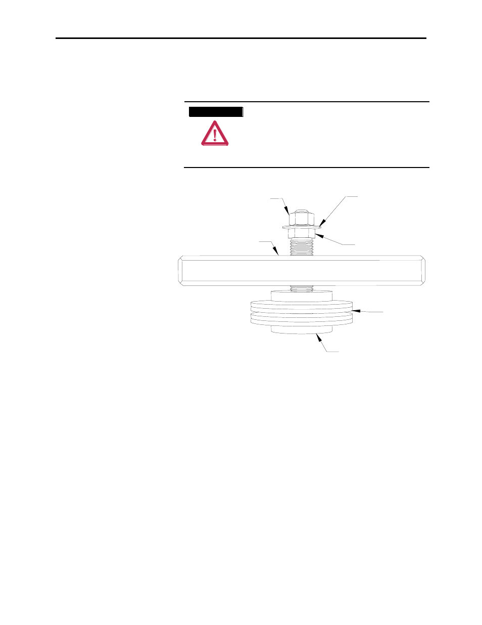
Calibration nut – DO NOT ADJUST
Indicating washer
Clamp bar
Adjusting nut
Disc springs
Pressure pad
Figure 6.19 – Clamp Head Illustration
If proper force (as designated on the clamp head block) is applied to
the clamping assembly, the indicating washer should just be able to
rotate with fingertip touch. The disc should not rotate freely. Some
force will need to be applied with your fingertips.
Clamping Pressure Adjustment
1. Ensure that all power to the drive is off.
2. Do not loosen the adjustment nut. If the clamping pressure is let
off, the assembly procedure must be carried out to ensure
uniform pressure on the thyristors.
3. Tighten with a 21-mm wrench on the adjustment nut (upward
motion) until the indicating washer can be turned by fingers with
some resistance. IT SHOULD NOT SPIN FREELY
.