Current transformerreplacement, Current transformer replacement – Rockwell Automation 7000 PowerFlex Medium Voltage AC Drive (B Frame) - Classic Control User Manual
Page 304
6-14
Component Definition and Maintenance
7000-UM150I-EN-P – June 2013
7000 “B” Frame
1. Ensure there is no power to the equipment.
A T T E N T I O N
A T T E N T I O N
To prevent electrical shock, ensure the main
power has been disconnected before working on
the current transformer. Verify that all circuits are
voltage free using a hot stick or appropriate
voltage-measuring device. Failure to do so may
result in injury or death.
2. Note the location of all wires and the orientation of the CT. For
quick reference when checking the orientation of the CT, look for the
white dot.
I M P O R T A N T
I M P O R T A N T
The CT and wires must be in the proper orientation.
Note the position before disassembly.
3. Disconnect the wires.
4. The bus bar must be disassembled to allow removal of the CT.
Remove the M10 hardware to allow the bus bar to slide out.
5. Remove the four screws located in the base of the CT and remove.
6. Replace the CT, ensuring the proper orientation. Fasten the CT
securely with the four screws in the base
7. Reconnect the ring lugs.
8. Replace the bus bar and tighten into place.
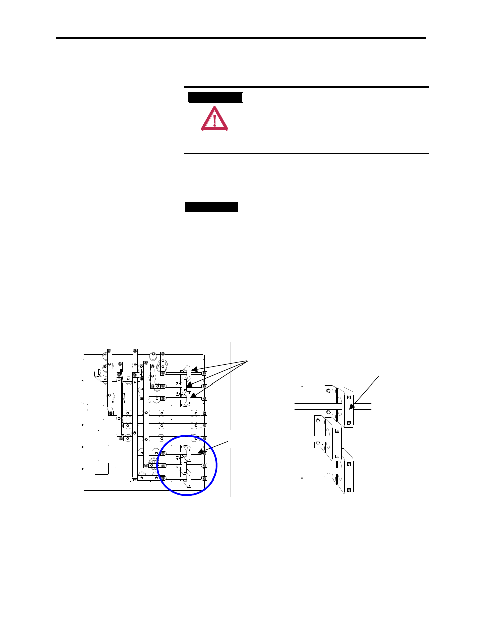
Detail:
Current Transformers (CT)
Bus Bar
Note the proper positioning of the
leads and CT before disassembly.
Figure 6.12 – Replacement of Current Transformer
Current Transformer
Replacement