Powercage removal (cont.) – Rockwell Automation 7000 PowerFlex Medium Voltage AC Drive (B Frame) - Classic Control User Manual
Page 328
6-38
Component Definition and Maintenance
7000-UM150I-EN-P – June 2013
7000 “B” Frame
3. Remove the 13-mm bolts in the two flanges that connect the
heatsink to the PowerCage, then remove the heatsink from the
PowerCage. This will reduce the weight of the PowerCage
making it easier to handle.
4. To detach the PowerCage itself, the bolts on the outer flange
need to be removed. Carefully lift the PowerCage down, placing
the forward face down. Do not overtorque these bolts when
replacing the PowerCage.
I M P O R T A N T
I M P O R T A N T
The PowerCage can be heavy and it is
preferred that two people should extract the
PowerCage from the drive to prevent injury
or damage to the module.
5. Refer to appropriate section for component replacement.
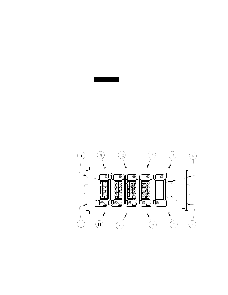
6. When replacing the PowerCage, it is important to place the bolts
on the outer flange in loosely. Torque bolts alternately on one
flange and then the opposite flange to ensure even tightening of
the module. A suggested sequence for torquing PowerCage bolts
is shown in Figure 6.25.
Note: The PowerCage is shown with switching components,
heatsinks and clamps removed for ease of lifting.
Figure 6.25 – Typical Torque sequence
7. Replace interior assembly in the reverse order of removal.
PowerCage Removal
(cont.)