Sharing resistors, Snubber and sharing resistor replacement (cont.) – Rockwell Automation 7000 PowerFlex Medium Voltage AC Drive (B Frame) - Classic Control User Manual
Page 332
6-42
Component Definition and Maintenance
7000-UM150I-EN-P – June 2013
7000 “B” Frame
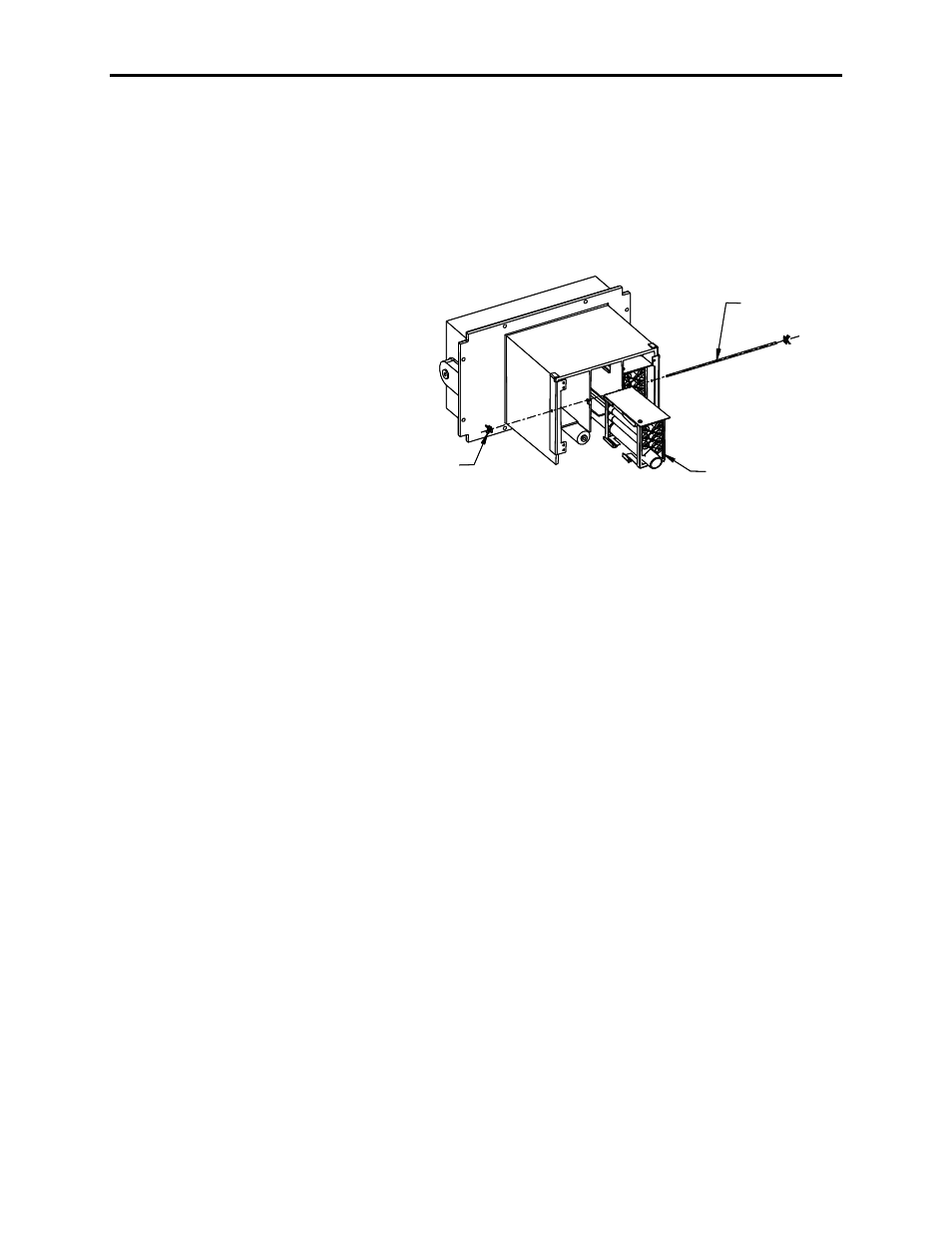
5. Silicon gel is used to secure the snubber resistor assembly to the
PowerCage. It is also used to minimize possible damages to the
resistor bank during transportation from the factory. It does not
need to be re-applied when inserting the new resistor bank.
Remove the resistor bank from the PowerCage.
Push Nut
Resistor Bank
Retaining Rod
Push Nut
Resistor Bank
Retaining Rod
Figure 6.29 – Removing resistor bank from PowerCage
6. Place the new resistor bank assembly back into the PowerCage.
7. Slide the retaining rod into place and push the clips back into
place.
8. Connect the leads to the resistor bank
9. Install the PowerCage as outlined in “PowerCage Removal”.
Sharing Resistors
Sharing resistors provide equal sharing of the voltage when matched
devices are used in series. SGCT PowerCages for 2300V systems do
not need matched devices and have no sharing resistor.
SCR PowerCages always have sharing resistors even if matched
devices are not required. Sharing resistors in SCR PowerCages
provide a diagnostic function.
Testing Sharing Resistors
It is possible to verify the resistance value of the sharing resistors
without removing the PowerCage from the cabinet. Follow the
procedures in Chapter 4 – Commissioning.
Snubber and Sharing
Resistor Replacement
(cont.)