Rockwell Automation 7000 PowerFlex Medium Voltage AC Drive (B Frame) - Classic Control User Manual
Page 457
Troubleshooting
7-35
7000 “B” Frame
7000-UM150I-EN-P – June 2013
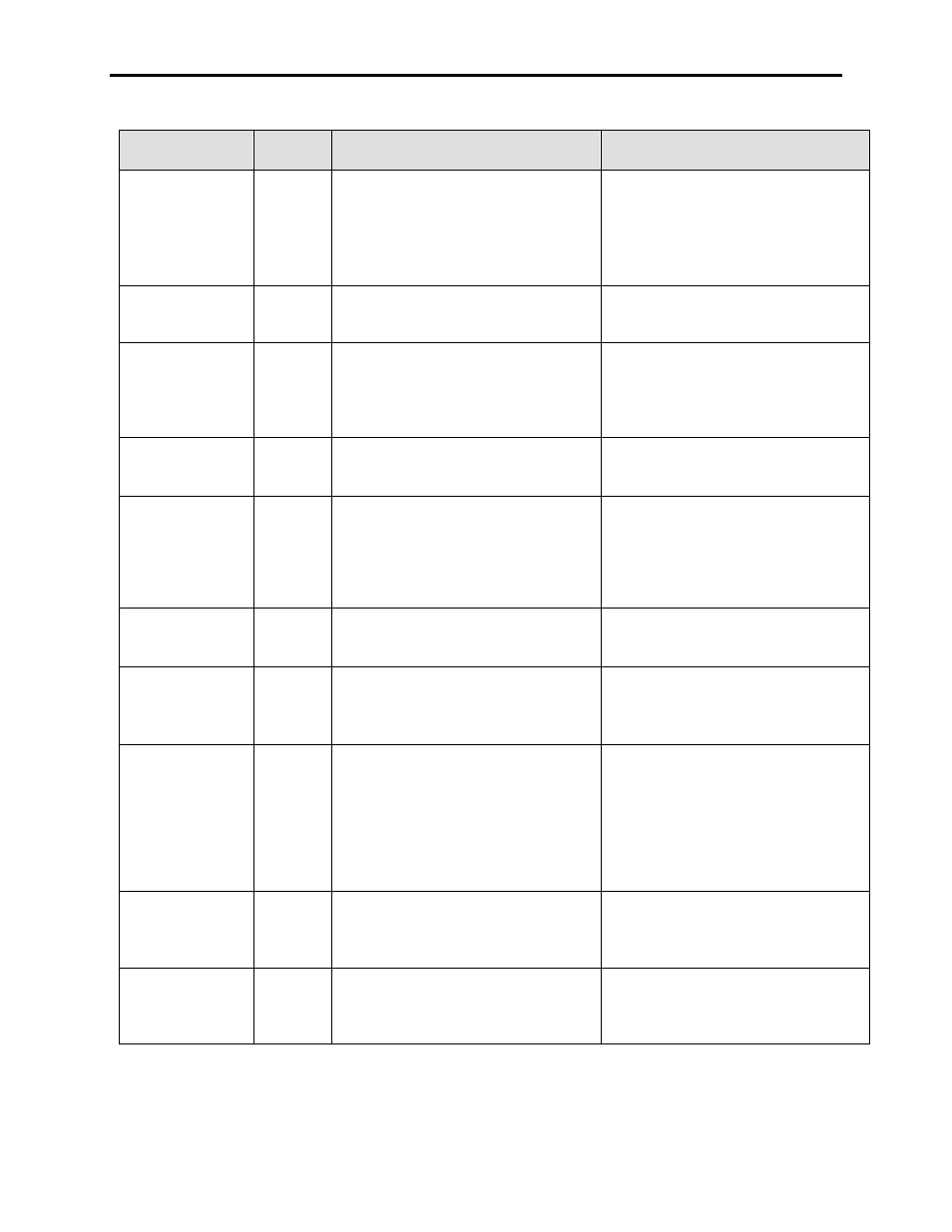
WARNING
MESSAGE
WARNING
CODE
DESCRIPTION
RECOMMENDED ACTIONS
DC Link Range
126
The value entered for the parameter Link
Inductance (P27) is below a minimum value
for the programmed Drive/Motor ratings.
6P Rectifier – 0.85 pu
18P Rectifier – 0.42 pu
PWM Rectifier – 0.55 pu
– Review DC Link nameplate data
– Review Motor and Drive nameplate data
and verify that all parameters were
entered properly
– Contact factory if the above seems OK
DcLnd Mstr
342
Slave Declined Master-slave only
– Slave has lost communication with hub
PLC, or slave is masked off in parameter
Master Mask
DCBL Battery Low
125
The PowerCap on the DCB-L that powers
the NVRAM where the parameters are
stored is below 2.6 V DC.
– Replace the PowerCap after recording
all the parameters to the terminal,
through Hyperterminal, with a printer or
with DriveTools
– Reinstall the parameters
DCBM Battery Low
188
The PowerCap on the DCB-M is below 2.6
V DC..
– This is not critical unless you ever put
this board in the rectifier position
– Replace the PowerCap
Desync Delay On
48
A transfer from the Line back to Drive
(desync) has been commanded, but it has
been less than 1 minute since the transfer
from Drive to Line (sync) was completed.
As a result, the Output Motor Filter Capacitors
have not had time to adequately discharge.
– Wait for 1 minute and attempt the
desync transfer again.
DPI Power Loss
109
The 12VDC used for SCANport/DPI
communications has dropped below the set
trip level.
– Verify DC/DC power supply output
– Confirm wiring to the CIB from the
DC/DC Power Supply
DPI Ram Overflow
163
DEVELOPMENT ERROR – There is an
internal communication error in the drive
control
– Noise/Grounding Issues
– Confirm grounding is per the RA
drawings
– Contact the Factory
Drive OL
111
A Line Overload warning has been detected,
where the overload condition is calculated
using DC Current Feedback (P322) and
Line Overload Warning (P270) as the point
where the overload warning occurs. (P270)
is programmed as a percentage of the
difference between Line Overload Minimum
(P269)and Line Overload Trip (P163).
– Transient Loading – Check torque limit
and overload settings and Compare
loading to torque settings and trip
settings
Drv in Test Mode
50
The drive Operating Mode (P4) is set to DC
Current Test Mode when an Autotune Test
that turns the motor is initiated
– Place drive back in Normal Mode before
attempting Autotune
Duplcte Mstr
341
Duplicate Master-master only
– The Powerup Config parameter is set to
Master in more than one drive. The first
drive to power up will become the
master