Impeller maintenance – Rockwell Automation 7000 PowerFlex Medium Voltage AC Drive (B Frame) - Classic Control User Manual
Page 348
6-58
Component Definition and Maintenance
7000-UM150I-EN-P – June 2013
7000 “B” Frame
Fan Installation
Care must be taken in handling of the fan as its balance could be
affected by poor handling.
Fan installation is performed in the reverse order of its removal.
Upon completion of installation, rotate the impeller by hand to
ensure that there is no contact with the inlet ring.
Impeller Maintenance
Impeller Removal from Motor Shaft
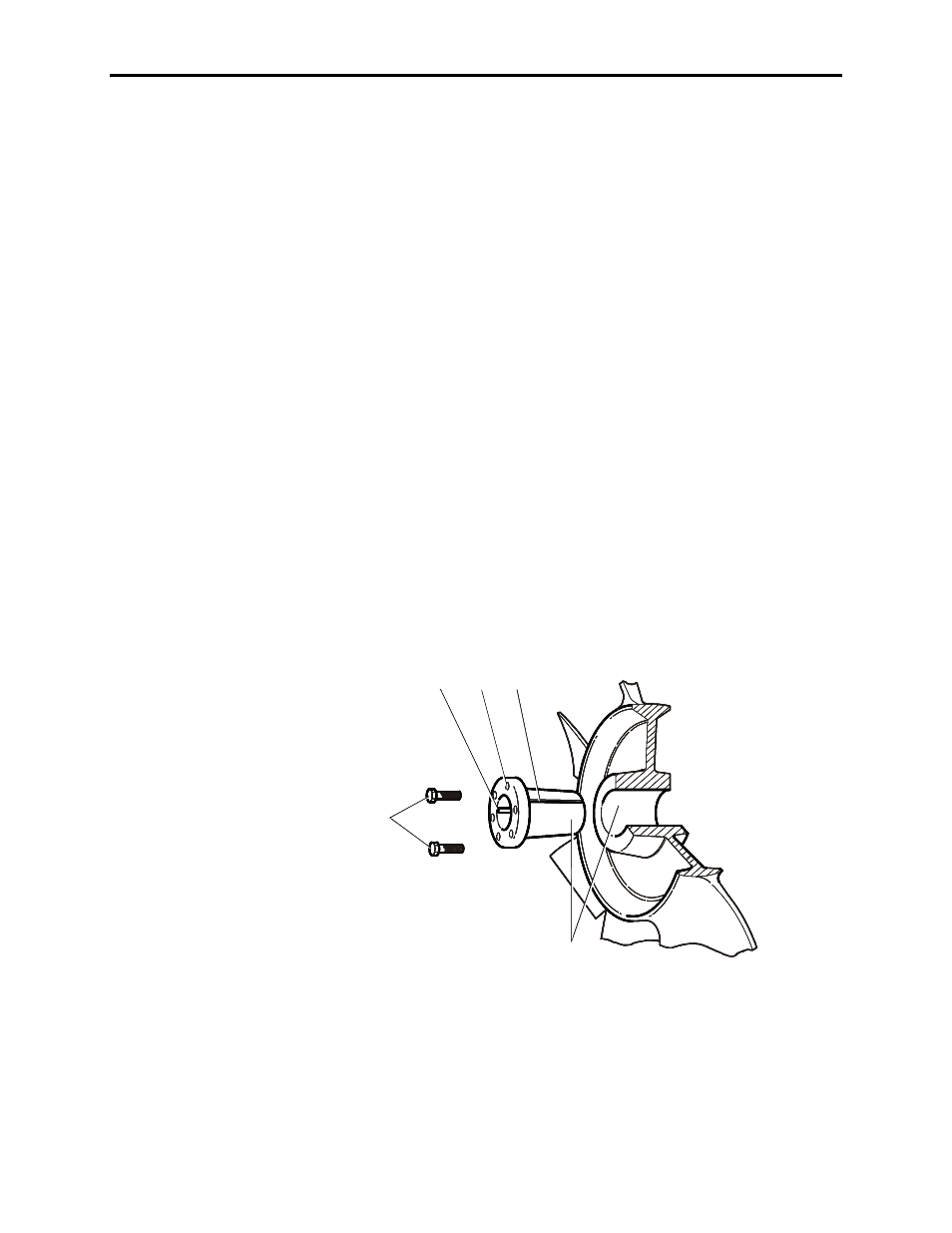
The fan impeller is held onto the motor shaft with a split tapered
bushing. This bushing is positioned on the motor shaft and through
the center of the impeller. Two capscrews, when tightened to
10.2 N-m (7.5 ft-lbs.), lock the bushing onto the motor shaft and
the impeller to the bushing.
Safety notes
The impeller is fragile. Do not allow the impeller to support the
weight of the motor.
If vertical, the impeller and bushing may fall when loosening
capscrews. Physical injury or component damage may result.
A
B
C
D
E
A – Taper surfaces
B – Capscrews
C – Split in Taper Bushing
D – Key
E – Threaded Hole for Separating Tapers
DO NOT LUBRICATE
CAPSCREWS, BORE
OR BUSHING BARREL
A
B
C
D
E
A
B
C
D
E
A – Taper surfaces
B – Capscrews
C – Split in Taper Bushing
D – Key
E – Threaded Hole for Separating Tapers
DO NOT LUBRICATE
CAPSCREWS, BORE
OR BUSHING BARREL
Figure 6.44 – Impeller Removal