Rockwell Automation 7000 PowerFlex Medium Voltage AC Drive (B Frame) - Classic Control User Manual
Page 337
Component Definition and Maintenance 6-47
7000 “B” Frame
7000-UM150I-EN-P – June 2013
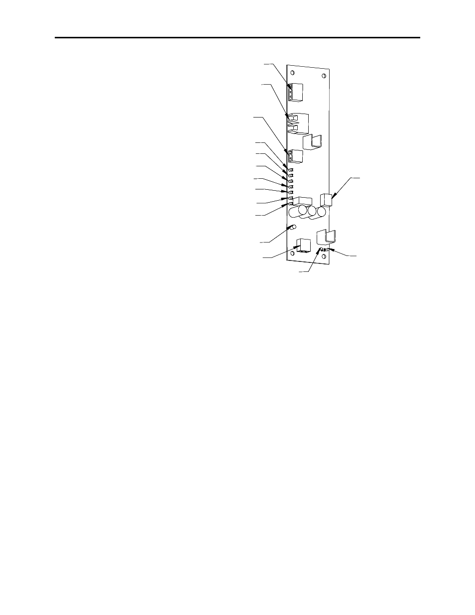
Test power connection
Fiber optic transmitter
and receiver
Thermal sensing
power connection
TP9
TP8
TP7
TP6
TP3
TP4
TP5
Gate and cathode
thyristor connection
LED
Snubber connection
TP1
TP2
TB3:
TB2:
TB4:
TB1:
Test power connection
Fiber optic transmitter
and receiver
Thermal sensing
power connection
TP9
TP8
TP7
TP6
TP3
TP4
TP5
Gate and cathode
thyristor connection
LED
Snubber connection
TP1
TP2
Test power connection
Fiber optic transmitter
and receiver
Thermal sensing
power connection
TP9
TP8
TP7
TP6
TP3
TP4
TP5
Gate and cathode
thyristor connection
LED
Snubber connection
TP1
TP2
TB3:
TB2:
TB4:
TB1:
Figure 6.33 – Self-Powered Gate Driver Board
Terminal/connections description
TB1-1 – Connection to SCR snubber circuit used to extract energy
from the snubber for SPGDB operation
TB1-2 – Connection to SCR sensing resistor which indicates
conduction status of SCR being operated
TB2-1 – Positive 20V power supply connection to temperature
sensor board. Provides power to temperature sensor board.
TB2-2 – Common connection of positive 20V power supply to
temperature sensor board
TB3-1 – Positive 15V power supply connection for test power
used when commissioning drive or testing SPGDB
TB3-2 – Provides artificial sense voltage signal to allow SPGDB
to gate the SCR when in test mode. When the appropriate
test power cable is used, P/N 81001-262-51, this input is
shorted to TB3-1 to obtain the sense voltage.
TB3-3 – Common connection of positive 15V power supply used
for test power
TB4-2 – Cathode connection to SCR being controlled
TB4-1 – Gate connection to SCR being controlled
OP1 –
Blue fiber optic cable receptacle – Firing pulse command
from the processor
OT1 –
Grey fiber optic cable receptacle – Diagnostic status of
the SCR