Rockwell Automation 1793-OE2S FLEX INTEGRA ANALOG MOD User Manual
Page 65
Publication 1793-6.5.1 - April 1999
Specifications
A-3
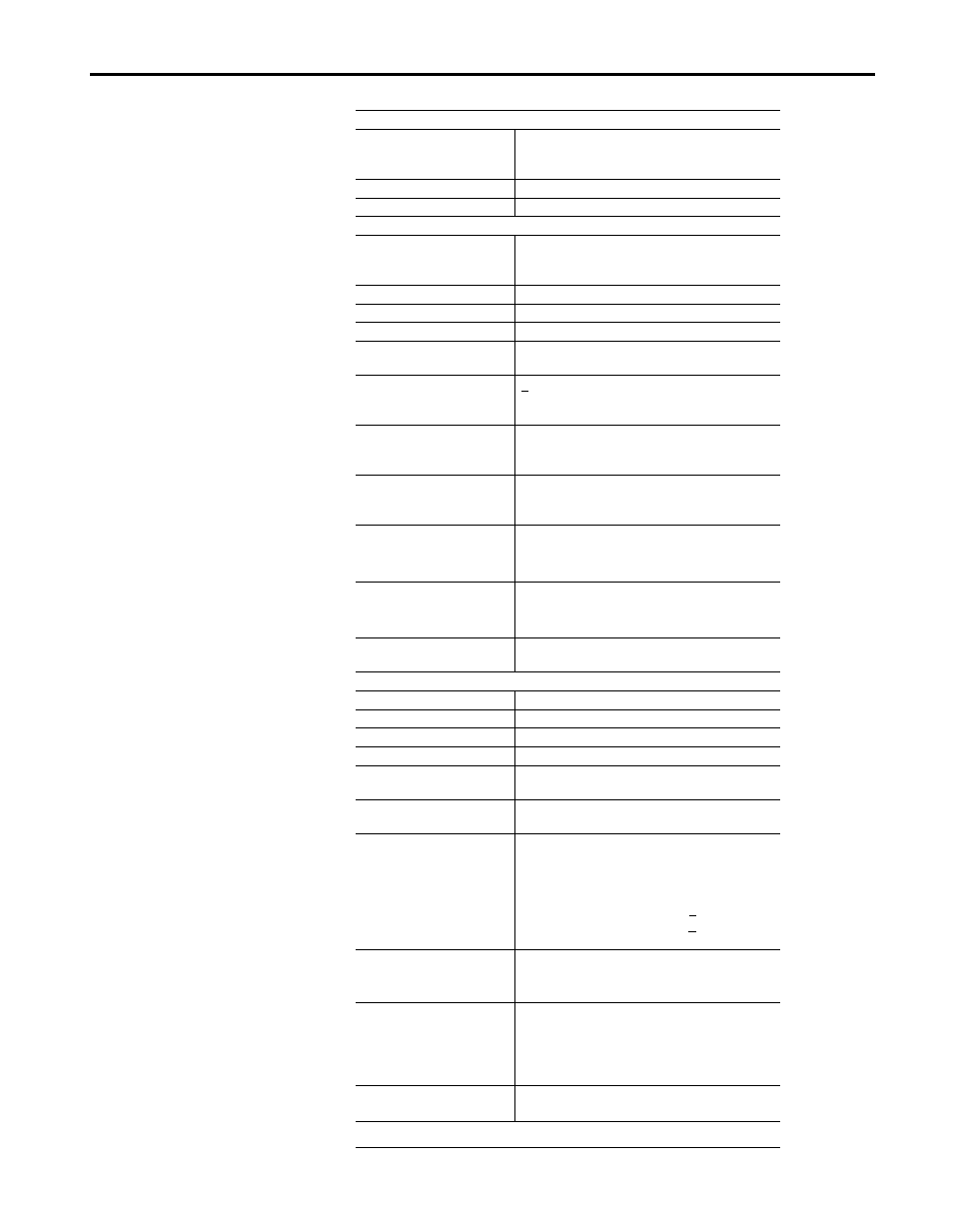
Specifications - 2 Output Analog Module, Cat. No. 1793-OE2 and -OE2S
Module Type
2 analog output
1793-OE2 - 16 screw-cage terminals
1793-OE2S - 16 spring-clamp terminals
Module Location
DIN rail mounting
Number of Channels
2 out - nonisolated
Output
Resolution
Voltage
Current
12-bits plus sign
2.56mV/cnt
5.13
μA/cnt
Data Format
left justified 16-bit 2’s complement
Conversion Type
Pulse width modulation
Conversion Rate
1.024ms all channels
Current Terminal
4-20mA (user configurable)
0-20mA (user configurable)
Voltage Terminal
+10V (user configurable)
0-10V (user configurable)
3A maximum
Step Response to 63%
Voltage Terminal
Current Terminal
24ms
24ms
Impedance
Voltage Terminal
Current Terminal
15-750
Ω resistive
15-750
Ω resistive
Absolute Accuracy
Voltage Terminal
Current Terminal
0.133% FS @ 25
o
C
0.425% FS @ 25
o
C
Accuracy Drift
Voltage Terminal
Current Terminal
0.0045% FS per
o
C
0.0069% FS per
o
C
Isolation Voltage
Channel to system - 850V dc for 1s
Channel to channel - None
General
Flexbus Current
20mA maximum
Power Dissipation
2.5W @ 31.2V dc
Thermal Dissipation
8.5 BTU/hr @ 31.2V dc
Indicators
1 green power indicators
External dc Power Voltage
Current
19.2-31.2V dc (5% ac ripple)
70mA maximum
Dimensions
in
(mm)
2.72H x 3.15D x 2.17W
(69H x 80D x 55W)
Environmental Conditions
Operational Temperature
Storage Temperature
Relative Humidity
Shock
Operating
Nonoperating
Vibration
0 to +55
o
C (32 to +131
o
F)
-40 to +85
o
C (-40 to +185
o
F)
5 to 95% noncondensing
Tested to 30g peak acceleration, 11(+1)ms pulse width
Tested to 50g peak acceleration, 11(+1)ms pulse width
Tested 5g @ 10-500Hz per IEC68-2-6
Conductors
Wire Size
Category
12 gauge (4mm
2
) stranded wire
3/64 in (1.2mm) maximum insulation
2
Agency Certification
(when product is marked)
• CSA certified
• CSA Class 1, Division 2 Groups A, B, C and D
certified
• UL listed
• CE marked for all applicable directives
Publications
• Installation Instructions - 1793-5.6
• User Manual - 1793-6.5.1
1
Use this category information for planning conductor routing as described in publication
1770-4.1, “Wiring and Grounding Guidelines for Noise Immunity.”