I/o structure, Adapter input status word – Rockwell Automation 1793-OE2S FLEX INTEGRA ANALOG MOD User Manual
Page 54
Publication 1793-6.5.1 - April 1999
Input, Status, Output and Configuration Files using ControlNet
6-3
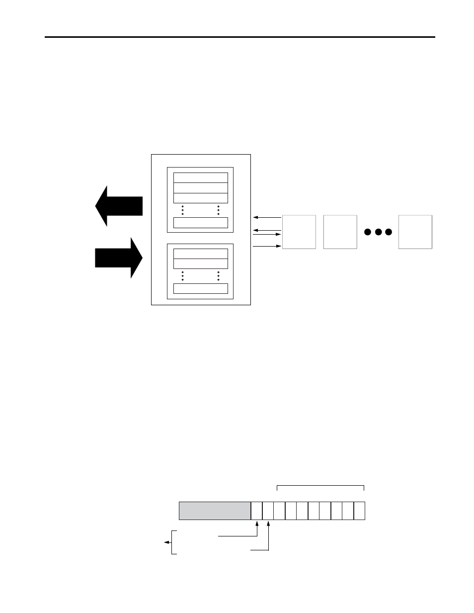
I/O Structure
Output data is received by the adapter in the order of the installed I/O
modules. The output data for slot 0 is received first, followed by the output
data for slot 1, and so on up to slot 7.
The first word of input data sent by the adapter is the Adapter status word.
This is followed by the input data from each slot, in the order of the
installed I/O modules. The input data from slot 0 is first after the status
word, followed by input data from slot 2, and so on up to slot 7.
Adapter Input Status Word
The input status word consists of:
• I/O module fault bits – 1 status bit for each slot
Additionally, in the case of a PLC-5 controller, it adds:
• node address changed – 1 bit (created by PLC-5 controller)
• I/O status – 1 bit (created by PLC-5 controller)
Resulting in the following ControlNet adapter status word for a
PLC-5 controller.
ControlNet Adapter
Read Data
Adapter Status
Slot 0 Input Data
Slot 1 Input Data
Slot 7 Input Data
Slot 0 Input Data
Slot 1 Input Data
Slot 7 Input Data
Write
Read
I/O
Module
Slot 0
I/O
Module
Slot 1
I/O
Module
Slot 7
Network READ
Network WRITE
41628
41629
Bit:
15
9
10 through 15
8
7
6
5
4
3
2
1
0
I/O Module Fault Bits
I/O Status Bit
Node Address Changed Bit
Created by PLC-5 controller