Rockwell Automation 1793-OE2S FLEX INTEGRA ANALOG MOD User Manual
Page 48
Publication 1793-6.5.1 - April 1999
How Communication Takes Place and I/O Image Table Mapping with the DeviceNet Adapter
5-9
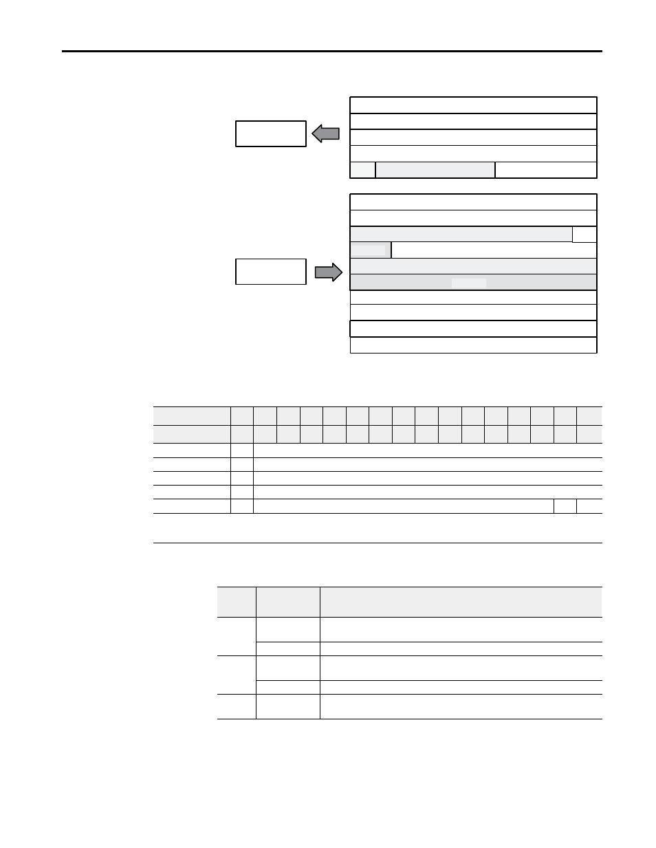
2 Input/1 Output Analog Combo Module (Cat. No. 1793-IE2XOE1 and -IE2XOE1S)
Analog Combo Module (1793-IE2XOE1 and -IE2XOE1S) Read
Word/Bit Descriptions for the 1793-IE2XOE1 and -IE2XOE1S Analog Combo
Module Read
odu e
age
I/O Image
Input Data Channel 0
Input Data Channel 1
Output Data Channel 0
Underrange & Diag.
Not used
Not used
Full Range and Configure Select
Not used
Input Size
Output Size
0 to 10 Words
0 to 5 Words
Read
Write
M
PU
Not used
Reserved
Reserved
Reserved
Reserved
Reserved
Reserved
Reserved
Word/Dec. Bit
15
14
13
12
11
10
09
08
07
06
05
04
03
02
01
00
Word/Octal Bit
17
16
15
14
13
12
11
10
07
06
05
04
03
02
01
00
Read Word 1
S
Analog Value Input Channel 0
Word 2
S
Analog Value Input Channel 1
Word 3
S
Reserved
Word 4
S
Reserved
Word 5
PU
Not used – set to 0
W1
W0
Where: S = sign bit (in 2’s complement)
W = Diagnostic bits for current output wire broken or load resistance high. (Not used on voltage outputs.)
PU = Power up bit
Word
Decimal Bit
(Octal Bit)
Definition
Read
Word 1
Bits 00-14
(00-16)
Channel 0 analog data – 12-bit left justified two’s complement number;
unused lower bits are zero; 4-20mA uses all 16 bits.
Bits 15 (17)
Channel 0 analog data sign bit.
Word 2
Bits 00-14
(00-16)
Channel 1 analog data – 12-bit left justified two’s complement number;
unused lower bits are zero; 4-20mA uses all 16 bits.
Bits 15 (17)
Channel 1 analog data sign bit.
Words 3
and 4
Reserved