Analog data format, Plc-2 programming – Rockwell Automation 1793-OE2S FLEX INTEGRA ANALOG MOD User Manual
Page 27
Publication 1793-6.5.1 - April 1999
Module Programming
3-5
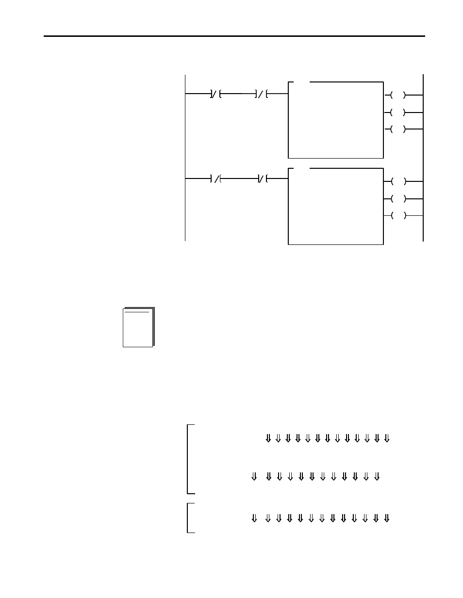
Figure 3.6
PLC-5 Family Sample Program Structure for the 1793-IE2XOE1
PLC-2 Programming
The 1793 analog I/O modules are not recommended for use with PLC-2
family programmable controllers due to the number of digits needed for
high resolution. In addition, the data returned from the analog-to-digital
converter in the module is 12-bit resolute. This value is left-justified into a
16-bit field, reserving the most significant bit for a sign bit. Refer to
Appendix B for more information.
Analog Data Format
The data returned from the analog-to-digital converter in the module is
12-bit resolute. This value is left-justified into a 16-bit field, reserving the
most significant bit for a sign bit.
BTR Enable Bit
EN
DN
BTW Enable Bit
1
2
ER
EN
DN
ER
BTR
BTW
Program Action
N16:5
15
N16:0
15
At power-up in RUN mode, or when the
processor is switched from PROG to RUN,
the user program enables a block transfer
read. Then it initiates a block transfer write
to configure the module and send data
values.
Thereafter, the program continuously
performs read block transfers and write block
transfers.
BTR Enable Bit
N16:0
15
BTW Enable Bit
N16:5
15
BLOCK TRANSFER READ
RACK:
2
GROUP:
3
MODULE:
0
CONTROL:
N16:0
DATA FILE:
N17:0
LENGTH:
5
CONTINUOUS:
N
BLOCK TRANSFER WRITE
RACK:
2
GROUP:
3
MODULE:
0
CONTROL:
N16:5
DATA FILE:
N17:5
LENGTH:
8
CONTINUOUS:
N
14 13 12 11 10 09 08 07 06 05 04 03 02 01 00
11 10 09 08 07 06 05 04 03 02 01 00
S
S
14 13 12 11 10 09 08 07 06 05 04 03 02 01 00
10 09 08 07 06 05 04 03 02 01 00
S
S
14 13 12 11 10 09 08 07 06 05 04 03 02 01 00
11 10 09 08 07 06 05 04 03 02 01 00
0*
A/D Unipolar Data
Analog Value
A/D Bipolar Data
Analog Value
D/A Data
Analog Value
*
= Always positive
Output
Input