Defaults – Rockwell Automation 1793-OE2S FLEX INTEGRA ANALOG MOD User Manual
Page 50
Publication 1793-6.5.1 - April 1999
How Communication Takes Place and I/O Image Table Mapping with the DeviceNet Adapter
5-11
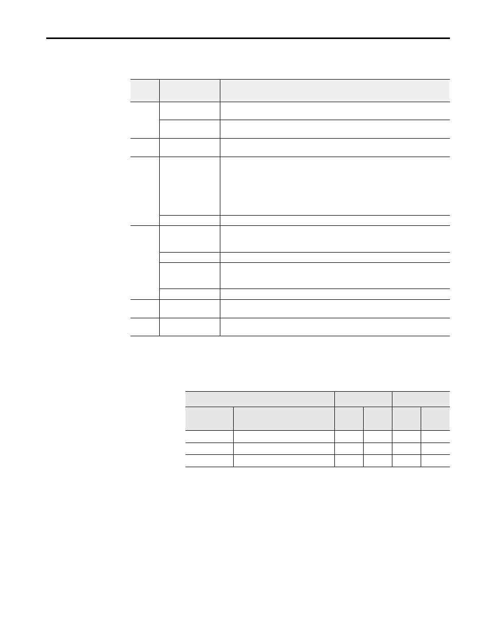
Word/Bit Descriptions for the 1793-IE2XOE1 and -IE2XOE1S Analog Combo
Module Write
Defaults
Each I/O module has default values associated with it. At default, each
module will generate inputs/status and expect outputs/configuration.
Factory defaults are the values assigned by the adapter when you:
• first power up the system, and
• no previous stored settings have been applied.
For analog modules, the defaults reflect the actual number of input words/
output words. For example, for the 4-input module, you have 11 input
words, and 4 output words.
Word
Decimal Bit
(Octal Bit)
Definition
Write
Word 1
Bits 00-14
(00-16)
Channel 0 analog data – 12-bit left justified two’s complement number; unused
lower bits are zero; 4-20mA uses all 16 bits.
Bits 15
(17)
Channel 0 analog data sign bit.
Word 2
Bits 00-15
(00-17
Reserved
Word 3
Bit 00
Multiplex control bits (M) for individual channel. This bit controls the safe state
analog outputs– Bit 00 corresponds to output channel 0.
1 = use words 0 (analog value) as directed by channel number n
0 = use words 6 (safe state analog value) as directed by channel number n
When bit 00 is cleared (0) simultaneously by a communication error or user choice
thru the programmable controller program, word 4 full range and configure select
bits are preserved at their last setting.
Bits 01-15 (01-17)
Not used – set to 0.
Word 4
Bits 00-01, 04
Full range bits (F) for individual channels – Bit 00 corresponds to input channel 0,
bit 01 corresponds to input channel 1, and bit 04 corresponds to output channel 1.
Refer to Range Bit Selections.
Bits 02, 03, 05-07
Not used – set to 0.
Bits 08-09, 12 (10,
11, 13-15)
Configure select bits (C) for individual channels – Bit 08 corresponds to input
channel 0, bit 09 (11) corresponds to input channel 1, bit 12 (14) corresponds to
output channel 0. Refer to Range Bit Selections.
Bits 14-15 (16-17)
Not used – set to 0.
Words 5
and 6
Bits 01-15 (01-17)
Not used – set to 0.
Words 7
thru 10
Bits 01-15 (01-17)
Reserved
Module Defaults for:
Factory Defaults
Real Time Size
Catalog
Number
Description
Input
Default
Output
Default
Input
Default
Output
Default
1793-IE4
4-Input Module
11
4
8
0
1793-OE2
2-Output Module
11
4
8
0
1793-IE2XOE1
2-Input/1 Output Module
11
4
8
0