Adapter input status word – Rockwell Automation 1793-OE2S FLEX INTEGRA ANALOG MOD User Manual
Page 41
Publication 1793-6.5.1 - April 1999
5-2
How Communication Takes Place and I/O Image Table Mapping with the DeviceNet Adapter
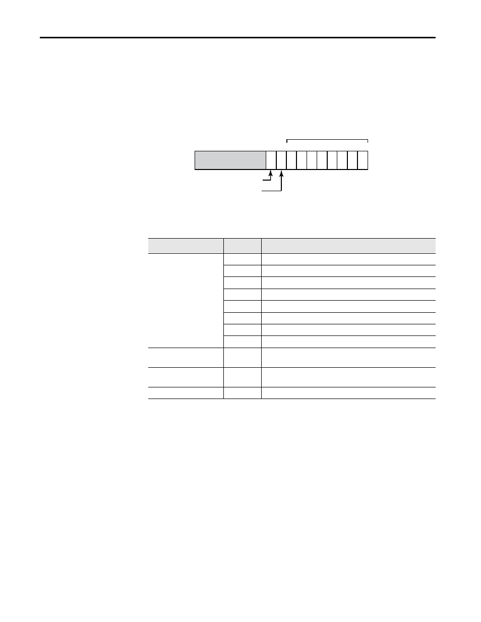
Adapter Input Status Word
The input status word consists of:
• I/O module fault bits – 1 status bit for each slot
• node address changed – 1 bit
• I/O status – 1 bit
The adapter input status word bit descriptions are shown in the following
table.
Possible causes for an I/O Module Fault are:
• transmission errors on the Flex I/O backplane
• a failed module
• a module removed from its terminal base
• incorrect module inserted in a slot position
• the slot is empty
The node address changed bit is set when the node address switch setting
has been changed since power up. The new node address does not take
affect until the adapter has been powered down and then powered back up.
15
Bit:
0
1
2
3
4
5
6
7
8
10 through 15
I/O Module Fault Bits
Node Address Changed Bit
Slot 0
Slot 1
Slot 2
Slot 3
Slot 4
Slot 5
Slot 6
Slot 7
9
I/O State Bit
Not Used
Bit Description
Bit
Explanation
I/O Module Fault
0
This bit is set (1) when an error is detected in slot position 0.
1
This bit is set (1) when an error is detected in slot position 1.
2
This bit is set (1) when an error is detected in slot position 2.
3
This bit is set (1) when an error is detected in slot position 3.
4
This bit is set (1) when an error is detected in slot position 4.
5
This bit is set (1) when an error is detected in slot position 5.
6
This bit is set (1) when an error is detected in slot position 6.
7
This bit is set (1) when an error is detected in slot position 7.
Node Address Changed
8
This bit is set (1) when the node address switch setting has been
changed since power up.
I/O State
9
Bit = 0 – idle
Bit = 1 – run
10 thru 15
Not used – sent as zeroes.