Rockwell Automation 1793-OE2S FLEX INTEGRA ANALOG MOD User Manual
Page 21
Publication 1793-6.5.1 - April 1999
How to Install Your Analog Module
2-9
5. Connect +24V dc to terminal 8 on row B
6. Connect 24V dc common to terminal 0 on row A.
7. If daisy-chaining +24V dc from this module to the next FLEX Integra
module, connect a jumper from terminal 15 to terminal 8 on the next
FLEX Integra module.
8. If daisy-chaining 24V dc common from this module to the next FLEX
Integra module, connect a jumper from terminal 7 on this module to
terminal 0 on the next Integra module.
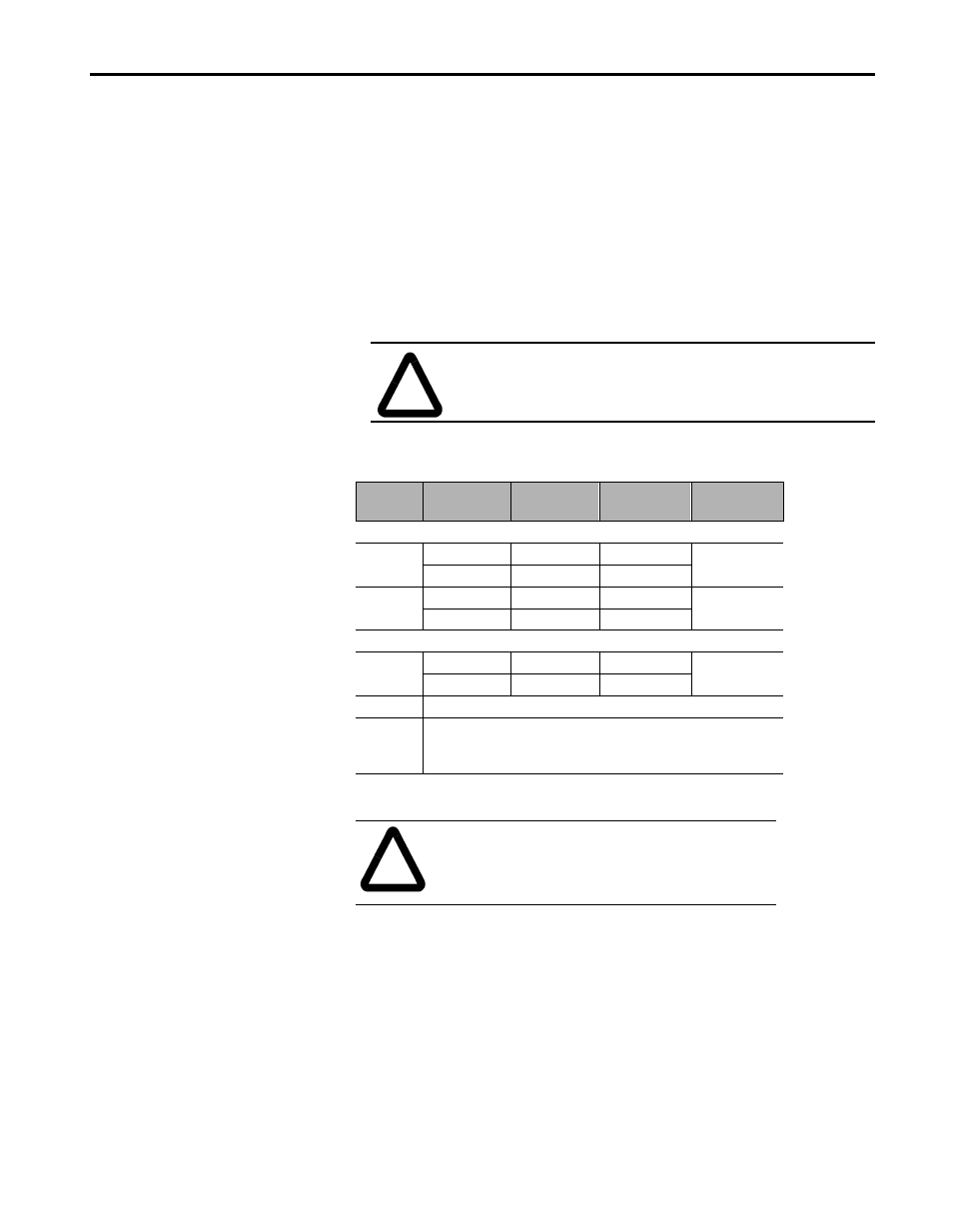
Table 2.C
Wiring connections for the 1794-IE4XOE2 Analog Module
ATTENTION: Total current draw through the terminal
base unit is limited to 10A. Separate power connections to
the terminal base unit may be necessary.
Channel
Signal Type
Label
Markings
Signal
Return
Input
0
Current
I
2
1
Voltage
V
3
1
Current
I
4
6
Voltage
V
5
Output
0
Current
I
10
9
Voltage
V
11
+24V dc
Terminals 8 and 15 are internally connected to +V.
24V dc
common
Terminals 0, 1, 6, 7, 9, 14 are internally connected together
in the module.
ATTENTION: Use a 100
Ω, 25W or greater,
resistor when connecting to a low-impedence
device, i.e., panel meter. Failure to do so can
result in damage to output circuitry.