Rockwell Automation 1793-OE2S FLEX INTEGRA ANALOG MOD User Manual
Page 35
Publication 1793-6.5.1 - April 1999
Writing Configuration to and Reading Status from Your Module with a Remote I/O Adapter
4-7
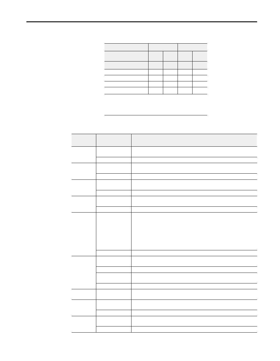
Range Selection Bits for the 1793-OE2 and -OE2S Analog Output Module (Word 5)
Word/Bit Descriptions for the 1793-OE2 and -OE2S Analog Output Module Write
Channel No.
Channel 0
Channel 1
F0
C0
F1
C1
Decimal Bits (Octal Bits)
00
08 (10)
01
09 (11)
4-20mA
0
1
0
1
0-10V dc/0-20mA
1
0
1
0
–10 to +10V dc
1
1
1
1
Off
1
0
0
0
0
C = Configure select bit
F = Full range bit
1
When configured to off, individual channels will send 0V or 0mV on
Series B modules. On Series A modules, 2V or 4mA is output until the
module is configured.
Word
Decimal Bit
(Octal Bit)
Definition
Write Word 0
Bits 00-14
(00-16)
Channel 0 analog data – 12-bit left justified two’s complement number; unused
lower bits are zero; 4-20mA uses all 16 bits.
Bits 15 (17)
Channel 0 analog data sign bit.
Word 1
Bits 00-14
(00-16)
Channel 1 analog data – 12-bit left justified two’s complement number; unused
lower bits are zero; 4-20mA uses all 16 bits.
Bits 15 (17)
Channel 1 analog data sign bit.
Word 2
Bits 00-14
(00-16)
Channel 2 analog data – 12-bit left justified two’s complement number; unused
lower bits are zero; 4-20mA uses all 16 bits.
Bits 15 (17)
Channel 2 analog data sign bit.
Word 3
Bits 00-14
(00-16)
Channel 3 analog data – 12-bit left justified two’s complement number; unused
lower bits are zero; 4-20mA uses all 16 bits.
Bits 15 (17)
Channel 3 analog data sign bit.
Word 4
Bits 00-03
Multiplex control bits (M) for individual channels. These bits control the safe
state analog outputs. – Bit 00 corresponds to output channel 0, bit 01
corresponds to output channel 1, and so on.
1 = use words 0 or 1 as directed by channel number n
0 = use words 10 or 11 as directed by channel number n
When bits 00-01 are all cleared (0) simultaneously by a communication error or
user choice thru the programmable controller program, word 5 full range and
configure select bits are preserved at their last setting.
Bits 04-15 (04-17)
Not used – set to 0.
Word 5
Bits 00-01
Full range bits (F) for individual channels – Bit 00 corresponds to output channel
0, and bit 01 corresponds to output channel 1.
Bits 02-07
Not used – set to 0.
Bits 08-09 (10-11)
Configure select bits (C) for individual channels – Bit 08 corresponds to output
channel 0, and bit 09 corresponds to output channel 1.
Bits 10-15 (12-17)
Not used – set to 0.
Words 6 thru 9
Bits 00-15
(00-17)
Not used – set to 0.
Word 10
Bits 00-14
(00-16)
Channel 0 Safe State analog value – 12-bit left justified two’s complement
number; unused lower bits are zero; 4-20mA uses all 16 bits.
Bits 15 (17)
Channel 0 Safe State analog data sign bit.
Word 11
Bits 00-14
(00-16)
Channel 1 Safe State analog value – 12-bit left justified two’s complement
number; unused lower bits are zero; 4-20mA uses all 16 bits.
Bits 15 (17)
Channel 1 Safe State analog data sign bit.