Range selection, Safe state value selection, Data format – Rockwell Automation 1793-OE2S FLEX INTEGRA ANALOG MOD User Manual
Page 30: Reading data from your module, Mapping data for the analog modules
Publication 1793-6.5.1 - April 1999
4-2
Writing Configuration to and Reading Status from Your Module with a Remote I/O Adapter
Range Selection
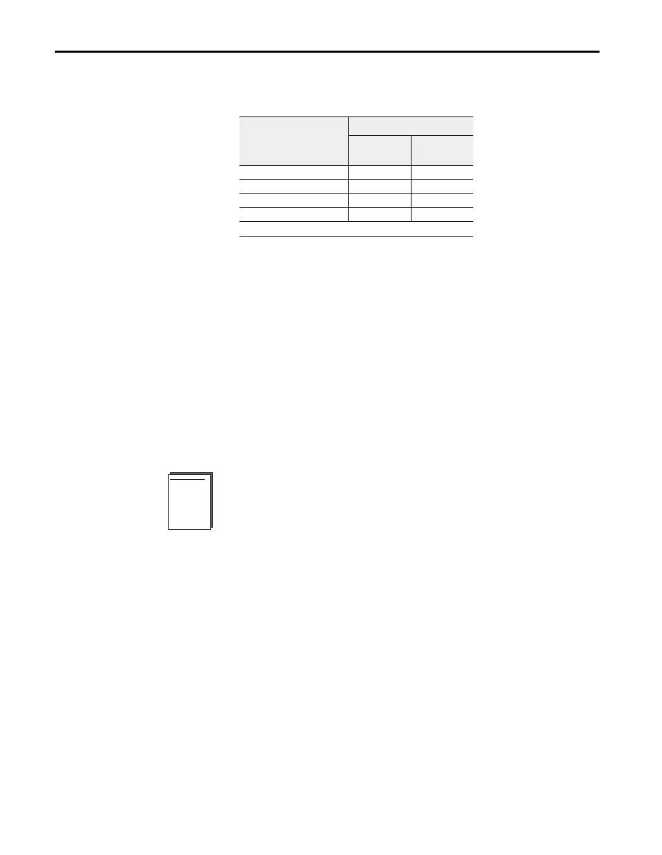
Individual input channels are configurable to operate with the following
voltage or current ranges:
You can select individual channel ranges using the designated words of the
write block transfer instruction. Refer to the Bit/Word description for your
particular module for word and bit numbers.
Safe State Value Selection
You can select the analog values that your output module will maintain in
the event of a network communication error. When the multiplex control
bits (M) are cleared simultaneously by a communication error, (or by the
user), the analog outputs will automatically switch to the values set in the
safe state analog words. This allows you to define a safe operating state for
controlled devices which depend on the analog output from the module.
Data Format
The data returned from the analog-to-digital converter in the module is
12-bit resolute. This value is left-justified into a 16-bit field, reserving the
most significant bit for a sign bit. The 4-20mA mode scales in the module
and uses all 16 bits.
Refer to Appendix C for a table of values for various current and voltage
modes, and an example of scaling to engineering terms.
Reading Data From Your
Module
Read programming moves status and data from the module to the
processor’s data table. The processor’s user program initiates the request to
transfer data from the input module to the processor.
Mapping Data for the
Analog Modules
The following read and write words and bit/word descriptions describe the
information written to and read from the analog modules. Each word is
composed of 16 bits.
Ranges
Bit Settings
Configure
Select
Full Range
0-10V dc/0-20mA
0
1
4-20mA
1
0
–10 to +10V dc
1
1
Off
0
0
1
When configured to Off, individual output channels will drive 0V/0mA.