Rockwell Automation 1793-OE2S FLEX INTEGRA ANALOG MOD User Manual
Page 34
Publication 1793-6.5.1 - April 1999
4-6
Writing Configuration to and Reading Status from Your Module with a Remote I/O Adapter
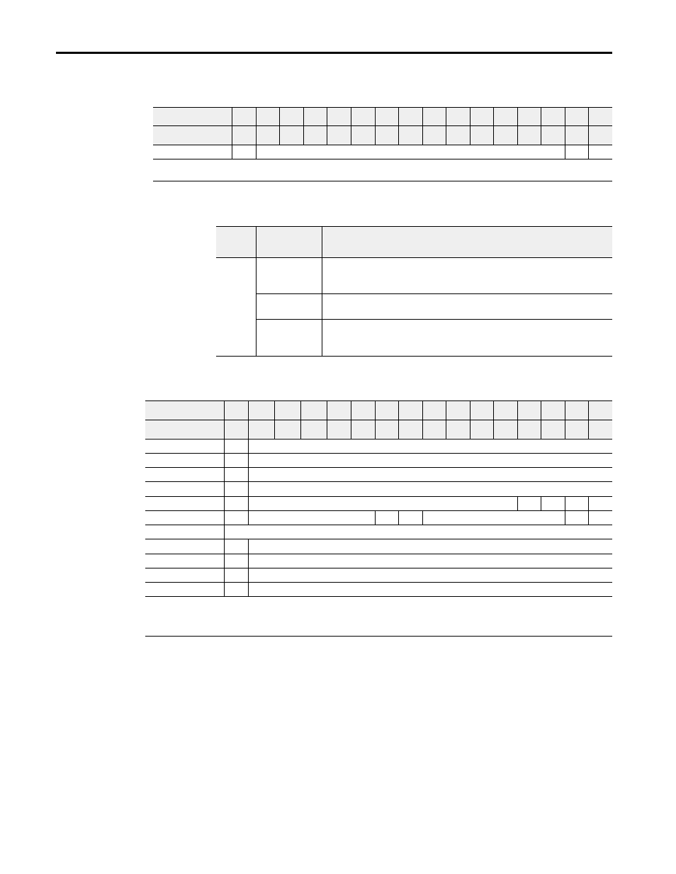
Analog Output Module (1793-OE2 and -OE2S) Read
Bit/Word Descriptions for the 1793-OE2 and -OE2S Analog Output Module Read
Analog Output Module (1793-OE2 and -OE2S) Write Configuration Block
Word/Dec. Bit
15
14
13
12
11
10
09
08
07
06
05
04
03
02
01
00
Word/Octal Bit
17
16
15
14
13
12
11
10
07
06
05
04
03
02
01
00
Read Word 0
PU
Not used – set to 0
W1
W0
Where: W = Diagnostic bits for current output wire broken or load resistance high. (Not used on voltage outputs.)
PU = Power up bit
Word
Decimal Bit
(Octal Bit)
Definition
Read
Word 0
Bits 00-01
Current outputs only – When set (1), the wire on the output is broken or the
load resistance is too high. Bit 00 corresponds to channel 0, bit 01
corresponds to channel 2, and so on.
Bits 02-14
(02-16)
Not used – set to 0
Bit 15 (17)
Power Up bit. - This bit is set to 1 when all bits in the configuration
register (write word 5) are 0 (unconfigured state). The configuration
register can be cleared by either a reset, or by the user writing all zeroes to it.
Word/Dec. Bit
15
14
13
12
11
10
09
08
07
06
05
04
03
02
01
00
Word/Octal Bit
17
16
15
14
13
12
11
10
07
06
05
04
03
02
01
00
Write Word 0
S
Analog Data – Channel 0
Word 1
S
Analog Data – Channel 1
Word 2
S
Reserved
Word 3
S
Reserved
Word 4
0
Not used – set to 0
M1
M0
Word 5
0
Not used – set to 0
C1
C0
Not used – set to 0
F1
F0
Word 6 thru 9
Not used – set to 0
Word 10
S
Safe State Value – Channel 0
Word 11
S
Safe State Value – Channel 1
Word 12
S
Reserved
Word 13
S
Reserved
Where: S = Sign bit (in 2’s complement)
M = Multiplex control
C = Configure select bit
F = Full range bit