Figure 22 - example dlr network – Rockwell Automation 1756-RMxx ControlLogix Enhanced Redundancy System User Manual User Manual
Page 87
Rockwell Automation Publication 1756-UM535D-EN-P - November 2012
87
Configure the EtherNet/IP Network
Chapter 4
Use An Enhanced
Redundancy System in a
Device-level Ring Topology
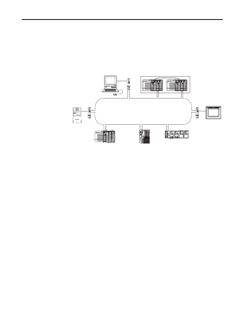
A DLR network is a single-fault tolerant ring network intended for the
interconnection of automation devices. This topology is implemented at the
device level because the use of EtherNet/IP embedded switch technology embeds
switches into the end devices themselves. No additional switches are required.
This graphic shows an example DLR network that includes an enhanced
redundancy system, revision 19.052 or later, connected to the network.
Figure 22 - Example DLR Network
Products with embedded switch technology have these features in common:
• Support for the management of network traffic to be sure of timely
delivery of critical data
• Designed according to the ODVA specification for EtherNet/IP
networks
• Ring recovery time less than 3 ms for DLR networks of 50 or fewer nodes
• Support for CIP Sync technology
• Two ports to connect to DLR networks in a single subnet
Devices on a DLR network can function on the network in these required roles:
• Supervisor Nodes - There are two types of supervisor nodes:
1. Active Supervisor Node - The network requires one active supervisor node
per DLR network that executes these tasks:
– Verifies ring integrity
– Reconfigures the ring to recover from a single fault
– Collects ring diagnostic information