Assembly structure – Rockwell Automation 1403-NDNET DeviceNet Communications Card Installation Instructions User Manual
Page 87
Publication 1403-IN054B-EN-P - August 2001
DeviceNet Data Tables B-57
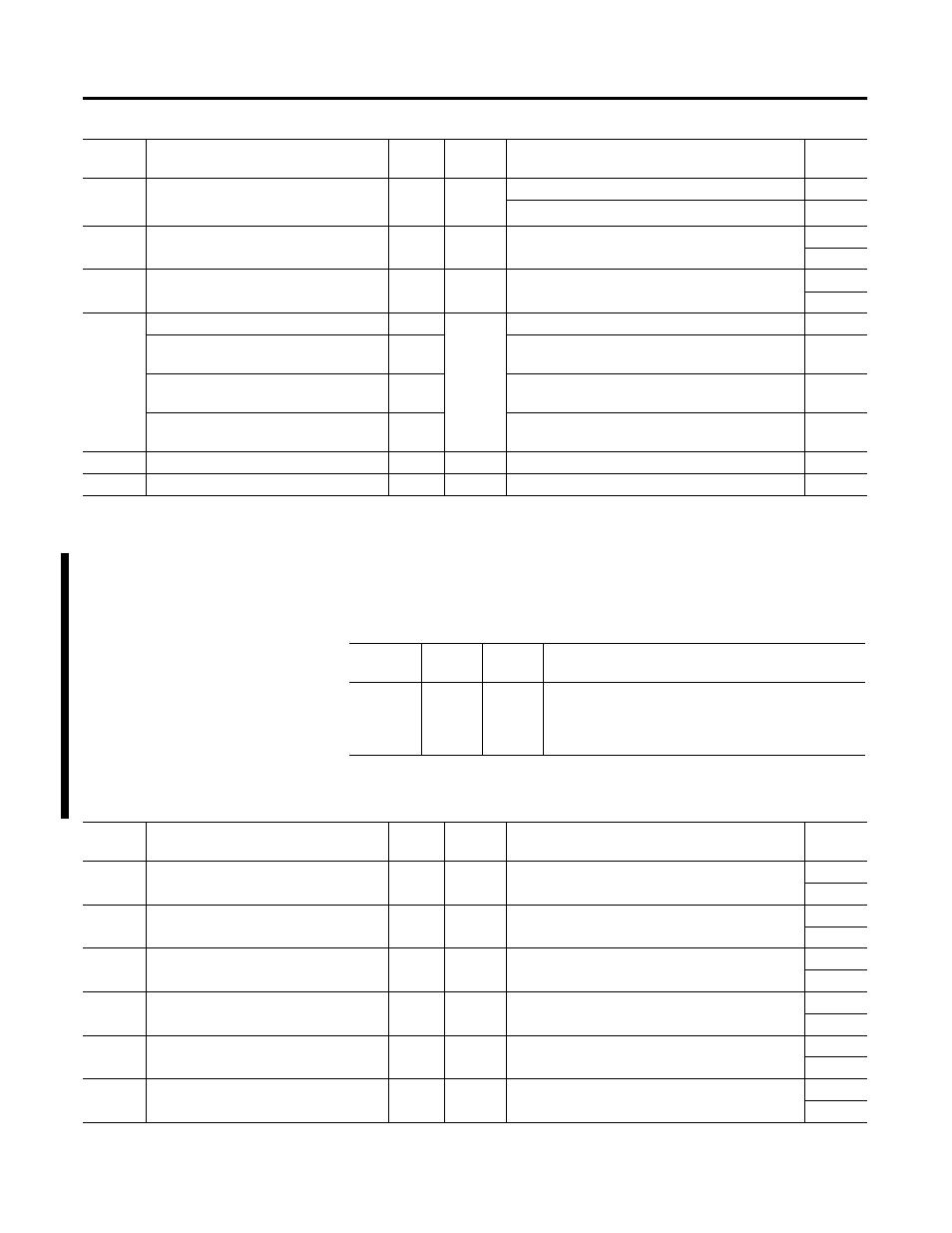
Instance 51 Attribute (Snapshot 16 parameter record; table 2 of 2)
Assembly Structure
7
L4 Current
Float
4
RMS current measured via the I4+/I4- terminals
13
Range = 0 to 9999x10
21
Amps
14
8
Voltage Unbalance
Float
4
Range = 0.0 to 100%
15
16
9
Current Unbalance
Float
4
Range = 0.0 to 100%
17
18
10
Record Timestamp; Year
Int
8
Year
19
Record Timestamp; Month, Day
Int
Month = Value/256
Day = Remainder of Value/256
20
Record Timestamp; Hour, Minute
Int
Hour = Value/256
Minute = Remainder of Value/256
21
Record Timestamp; Seconds, hSeconds
Int
Seconds = Value/256
Hseconds = Remainder of Value/256
22
11
Snashot record # being returned
Int
2
Range 1 to 265
23
12
Unused
Int
2
0
24
Param
#
Parameter name
Data
Type
# bytes
Description
Word
No.
Attribute
ID
Access
Rule
Name
DeviceNet
Data Type
3
Get
Data
Structure of
40 bytes; 20 words
Note: this table is only supported when master module
firmware is V3.00 or later
Param
#
Parameter name
Data
Type
# bytes
Description
Word
No.
1
Total Real Power
Float
4
Range = 0 to 9999x10
21
W
1
2
2
Total Reactive Power
Float
4
Range = 0 to 9999x10
21
VAR
3
4
3
Demand W
Float
4
Range = 0 to 9999x10
21
W
5
6
4
Demand VAR
Float
4
Range = 0 to 9999x10
21
VAR
7
8
5
Total True PF
Float
4
Range = -100 to 100%
9
10
6
Wh net
Float
4
Range = -9999 x10
21
to 9999x10
21
Wh
11
12