10 using i/o messaging – Rockwell Automation 1203-EN1 EtherNet/IP-to-SCANport Module User Manual
Page 62
5-10
Using I/O Messaging
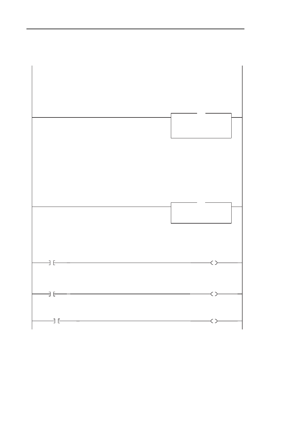
Figure 5.5 Example ControlLogix Ladder Logic Program for I/O Messaging (Cont.)
This rung displays the Feedback word from the 1305 drive. Note that the value is in an engineering unit, where "32,767"
equals the Parameter 19 [Maximum Freq] value and "0" equals 0 Hz. The relationship is linear. For example, if Parameter
19 = 60 Hz (default setting), then:
32,767 = 60 Hz
16,384 = 30 Hz
8,192 = 15 Hz
4,096 = 7.5 Hz
0 = 0 Hz (etc.)
6
Move
Source AB1305_Drive:I.Data[3]
16384
Dest
Feedback
16384
MOV
1305
Feedback
This rung displays the Feedback word from the 1305 drive. Note that the value is in an engineering unit, where "32,767"
equals the Parameter 19 [Maximum Freq] value and "0" equals 0 Hz. The relationship is linear. For example, if Parameter
19 = 60 Hz (default setting), then:
32,767 = 60 Hz
16,384 = 30 Hz
8,192 = 15 Hz
4,096 = 7.5 Hz
0 = 0 Hz (etc.)
Datalink data from drive. This rung is used for display purposes only. The AB1305_Drive:I.Data[*] tags could be used
directly elsewhere in the ladder program.
AB1305_Drive:I.Data[4] = Datalink A1 1305 Pr.111 = 7 [Accel Time 1]
AB1305_Drive:I.Data[5] = Datalink A2 1305 Pr.112 = 8 [Decel Time 1]
AB1305_Drive:I.Data[6] = Datalink B1 1305 Pr.113 = 10 [Stop Select]
AB1305_Drive:I.Data[7] = Datalink B2 1305 Pr.114 = 24 [Jog Frequency]
AB1305_Drive:I.Data[8] = Datalink C1 1305 Pr.115 = 27 [Preset Freq 1]
AB1305_Drive:I.Data[9] = Datalink C2 1305 Pr.116 = 28 [Preset Freq 2]
AB1305_Drive:I.Data[10] = Datalink D1 1305 Pr.117 = 29 [Preset Freq 3]
AB1305_Drive:I.Data[11] = Datalink D2 1305 Pr.118 = 73 [Preset Freq 4]
7
Copy File
Source AB1305_Drive:I.Data[4]
Dest
Datalinks_from_Drive[0]
Length
8
COP
Pr.7 Accel Time 1
Datalink data from drive. This rung is used for display purposes only. The AB1305_Drive:I.Data[*] tags could be used
directly elsewhere in the ladder program.
AB1305_Drive:I.Data[4] = Datalink A1 1305 Pr.111 = 7 [Accel Time 1]
AB1305_Drive:I.Data[5] = Datalink A2 1305 Pr.112 = 8 [Decel Time 1]
AB1305_Drive:I.Data[6] = Datalink B1 1305 Pr.113 = 10 [Stop Select]
AB1305_Drive:I.Data[7] = Datalink B2 1305 Pr.114 = 24 [Jog Frequency]
AB1305_Drive:I.Data[8] = Datalink C1 1305 Pr.115 = 27 [Preset Freq 1]
AB1305_Drive:I.Data[9] = Datalink C2 1305 Pr.116 = 28 [Preset Freq 2]
AB1305_Drive:I.Data[10] = Datalink D1 1305 Pr.117 = 29 [Preset Freq 3]
AB1305_Drive:I.Data[11] = Datalink D2 1305 Pr.118 = 73 [Preset Freq 4]
Logic Command bit control rungs are provided for display purposes only. The AB1305_Drive:O.Data[0].x bits could be used
directly elsewhere in the ladder program.
8
Stop_Command
1305
Logic Command
STOP
AB1305_Drive:O.Data[0].0
Logic Command bit control rungs are provided for display purposes only. The AB1305_Drive:O.Data[0].x bits could be used
directly elsewhere in the ladder program.
9
Start_Command
1305
Logic Command
START
AB1305_Drive:O.Data[0].1
10
ClearFault_Command
1305
Logic Command
CLEAR FAULTS
AB1305_Drive:O.Data[0].3