Chapter 1, Getting started, Components – Rockwell Automation 1203-EN1 EtherNet/IP-to-SCANport Module User Manual
Page 13: Components -1, 1getting started, Chapter
Chapter
1
Getting Started
The 1203-EN1 EtherNet/IP-to-SCANport module is a communication
option intended for use with Allen-Bradley drives and other products
that support SCANport.
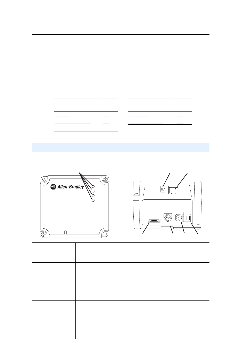
Figure 1.1 Components of the Module
Topic
Page
Topic
Page
Components
Item Part
Description
➊
Status Indicators
Four LEDs that indicate the status of the EtherNet/IP connection, SCANport,
and the module itself. Refer to
,
➋
Web Pages
Switch (SW2)
Enables and disables the module web pages. Refer to
. SW1 is unused.
➌
Ethernet
Connector
An RJ-45 connector for the Ethernet cable. The connector is CAT-5 compliant
to ensure reliable data transfer on 100Base-TX Ethernet connections.
➍
24 VDC Power
Terminal Block
24 VDC (+15% / -25%) power connection. If the 20-XCOMM-AC-PS1 is used,
this terminal block can be used to daisy-chain 24 VDC to other 1203-EN1’s.
➎
AC-to-DC Converter
Connector
Connection for optional 20-XCOMM-AC-PS1 AC-to-DC converter.
➏
SCANport
Connector
A 20-pin, single-row shrouded male header. An interface cable is
factory-connected to this connector and to a connector on the power supply
board in the 1203-EN1 enclosure base.
➐
RS232 DF1 Port
Used to connect software tools using 1203-SFC cable.
➋
➏
➐
➍
➎
➌
Front View
Bottom View
+ -
➊
1
2
O
N
Serial
SCANport
DC
ADP
DC
+
-
PORT
MOD
NET A
NET B
1203-EN1
EtherNet/IP to SCANport
10/100 Mbps