Example controllogix ladder logic program, Using i/o messaging 5-9 – Rockwell Automation 1203-EN1 EtherNet/IP-to-SCANport Module User Manual
Page 61
Using I/O Messaging
5-9
Example ControlLogix Ladder Logic Program
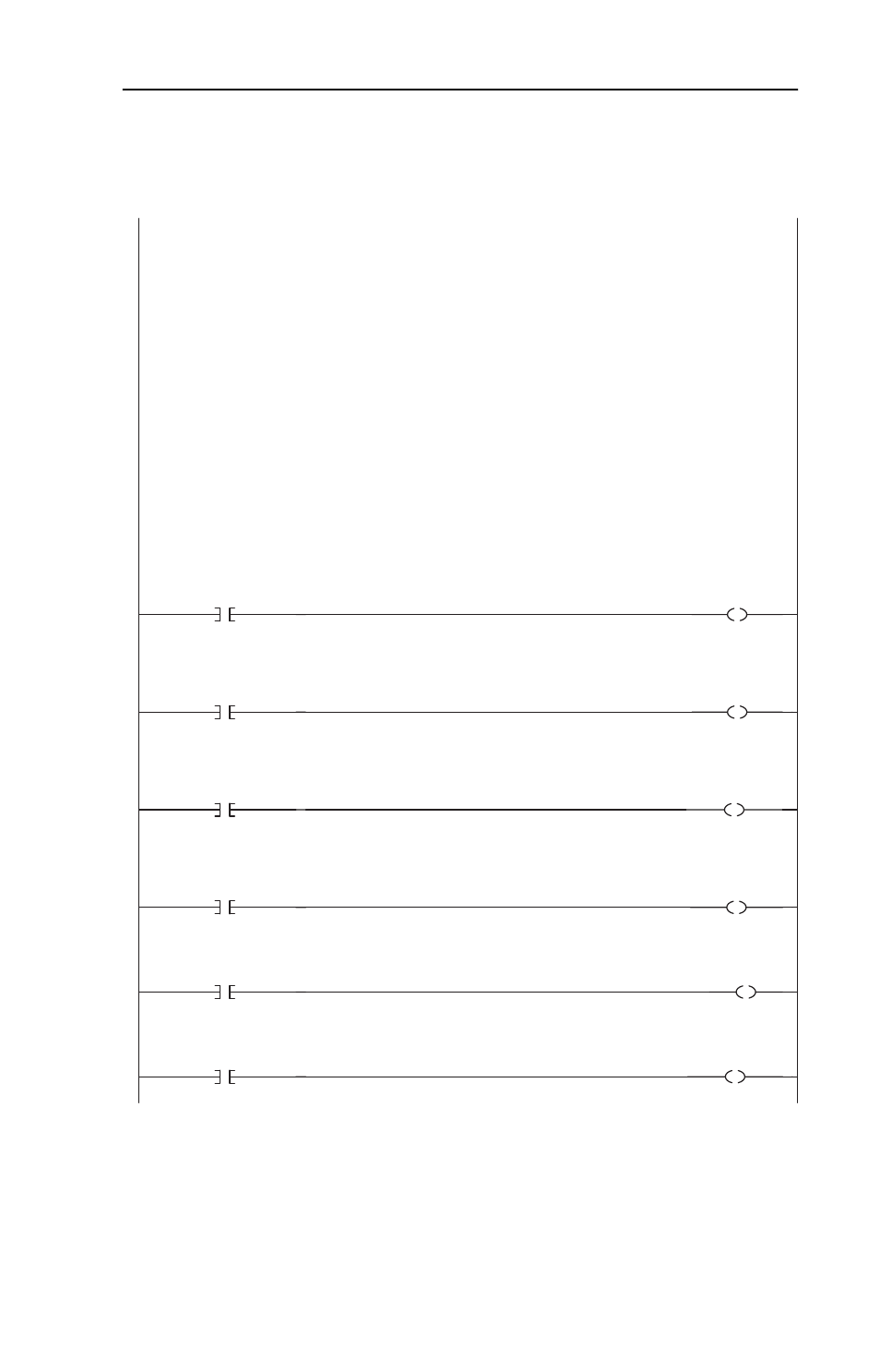
Figure 5.5 Example ControlLogix Ladder Logic Program for I/O Messaging
ControlLogix to 1305 drive on EtherNet/IP
The ControlLogix system consists of a 1756-ENBT in slot 5 communicating over EtherNet/IP with a 1305 drive using a
1203-EN1 EtherNet/IP module.
The I/O image is as follows:
INPUT (12 INT words) OUTPUT (10 INT words)
AB1305_Drive:I.Data[0] = ENBT Overhead AB1305_Drive:O.Data[0] = Drive Logic Command
AB1305_Drive:I.Data[1] = ENBT Overhead AB1305_Drive:O.Data[1] = Drive Reference
AB1305_Drive:I.Data[2] = Drive Logic Status AB1305_Drive:O.Data[2] = Datalink A1
AB1305_Drive:I.Data[3] = Drive Feedback AB1305_Drive:O.Data[3] = Datalink A2
AB1305_Drive:I.Data[4] = Datalink A1 AB1305_Drive:O.Data[4] = Datalink B1
AB1305_Drive:I.Data[5] = Datalink A2 AB1305_Drive:O.Data[5] = Datalink B2
AB1305_Drive:I.Data[6] = Datalink B1 AB1305_Drive:O.Data[6] = Datalink C1
AB1305_Drive:I.Data[7] = Datalink B2 AB1305_Drive:O.Data[7] = Datalink C2
AB1305_Drive:I.Data[8] = Datalink C1 AB1305_Drive:O.Data[8] = Datalink D1
AB1305_Drive:I.Data[9] = Datalink C2 AB1305_Drive:O.Data[9] = Datalink D2
AB1305_Drive:I.Data[10] = Datalink D1
AB1305_Drive:I.Data[11] = Datalink D2
This matches the I/O Configuration for the ETHERNET-MODULE AB1305_Drive (click on it and you will see that the
connection size for Inputs is set to 12 and Outputs is set to 10).
Logic Status information rungs are provided for display purposes only. The AB1305_Drive:I.Data[2].x bits could be used
directly elsewhere in the ladder program.
0
1305
Logic Status
ENABLED
AB1305_Drive:I.Data[2].0
1305
ENABLED
Drive_Ready
The ControlLogix system consists of a 1756-ENBT in slot 5 communicating over EtherNet/IP with a 1305 drive using a
1203-EN1 EtherNet/IP module.
The I/O image is as follows:
INPUT (12 INT words) OUTPUT (10 INT words)
AB1305_Drive:I.Data[0] = ENBT Overhead AB1305_Drive:O.Data[0] = Drive Logic Command
AB1305_Drive:I.Data[1] = ENBT Overhead AB1305_Drive:O.Data[1] = Drive Reference
AB1305_Drive:I.Data[2] = Drive Logic Status AB1305_Drive:O.Data[2] = Datalink A1
AB1305_Drive:I.Data[3] = Drive Feedback AB1305_Drive:O.Data[3] = Datalink A2
AB1305_Drive:I.Data[4] = Datalink A1 AB1305_Drive:O.Data[4] = Datalink B1
AB1305_Drive:I.Data[5] = Datalink A2 AB1305_Drive:O.Data[5] = Datalink B2
AB1305_Drive:I.Data[6] = Datalink B1 AB1305_Drive:O.Data[6] = Datalink C1
AB1305_Drive:I.Data[7] = Datalink B2 AB1305_Drive:O.Data[7] = Datalink C2
AB1305_Drive:I.Data[8] = Datalink C1 AB1305_Drive:O.Data[8] = Datalink D1
AB1305_Drive:I.Data[9] = Datalink C2 AB1305_Drive:O.Data[9] = Datalink D2
AB1305_Drive:I.Data[10] = Datalink D1
AB1305_Drive:I.Data[11] = Datalink D2
This matches the I/O Configuration for the ETHERNET-MODULE AB1305_Drive (click on it and you will see that the
connection size for Inputs is set to 12 and Outputs is set to 10).
Logic Status information rungs are provided for display purposes only. The AB1305_Drive:I.Data[2].x bits could be used
directly elsewhere in the ladder program.
1
1305
Logic Status
RUNNING
AB1305_Drive:I.Data[2].1
1305
RUNNING
Drive_Active
2
1305
Logic Status
COMMAND
DIRECTION
AB1305_Drive:I.Data[2].2
1305
FORWARD
Drive_Forward
3
/
1305
Logic Status
COMMAND
DIRECTION
AB1305_Drive:I.Data[2].2
1305
REVERSE
Drive_Reverse
4
1305
Logic Status
FAULT
AB1305_Drive:I.Data[2].7
1305
FAULT
Drive_Fault
5
1305
Logic Status
AT SPEED
AB1305_Drive:I.Data[2].8
1305
AT SPEED
Drive_At_Speed