Lon communication heartbeat, Theory of operation – Det-Tronics EQP Fire and Gas Detection/Releasing System User Manual
Page 8
14.1
95-8533
2-2
Lon CommuniCation HEaRtBEat
The Controller continuously broadcasts a heartbeat
signal over the LON loop. This heartbeat is used for
verifying the integrity of the LON loop and for keeping
the field devices from going into a fault isolation
mode. Once every second, the heartbeat contains the
current time and date, which are used by the field
devices to log status events and calibrations.
The Controller continuously tests LON continuity by
sending out a heartbeat on one LON port and then
listening for it on the other LON port. The Controller
also broadcasts the heartbeat signal in the opposite
direction around the loop. This ensures that all field
devices, the LON Network Extenders (NE), and
communication wiring are correctly passing the digital
information around the loop.
The field devices use the heartbeat as a mechanism
to ensure that there is a communication path back to
the Controller. If the field device does not receive a
heartbeat for a period of time, the device will go into a
LON fault isolation. In this situation, the device opens
one side of the LON and listens for a heartbeat on the
other side. If the device doesn’t receive a heartbeat, it
listens on the other side of the LON and opens the
opposite LON connection.
tHEoRY oF opERation
During normal operation, the Controller continuously
checks the system for fault conditions and executes
user defined programmed logic that coordinates the
control of the field devices. At the same time, the field
devices are continuously monitoring for device based
fault and alarm conditions.
When a fault condition occurs, the Controller displays
the fault condition on the Vacuum Fluorescent Text
Display, activates the appropriate fault LED(s),
activates the Trouble signal using the Controller’s
internal enunciator, and de-energizes the Controller’s
Trouble relay.
CONFIGURATION
PC
MODBUS
INTERFACE
NETWORK
EXTENDER
DIGITAL
COMMUNICATION
UNITS
PIRECL
GAS
DETECTOR
UD10 / DCU
OPECL
GAS
DETECTOR
SIGNAL
AUDIBLE
MODULES
HORNS
&
BEACONS
GAS DETECTION
COMBUSTIBLE, TOXIC,
POINTWATCH OR
OTHER 4-20 MA INPUT
RS-232
RS-232
RS-232
RS-485
RS-485
8 DRY CONTACT INPUTS
8 RELAY
OUTPUT POINTS
UNSUPERVISED INPUTS AND OUTPUTS
8 CHANNEL DCIO MODULE
DRY CONTACT INPUTS
CONFIGURABLE
OUTPUT POINTS
CONFIGURABLE INPUTS AND OUTPUTS
FIRE DETECTION
UV
DETECTOR
UVHT/C7050
DETECTOR
X3301
DETECTOR
X3302
DETECTOR
UV/IR
DETECTOR
IR
DETECTOR
INITIATING
DEVICE
CIRCUIT
CONTACT
CLOSURE
DEVICES
SIGNALING LINE CIRCUIT (SLC)
HARDWIRED I/O
SERIAL INTERFACE
EQP CONTROLLER
CONTROLNET
(OPTIONAL
INTERFACE)
ONBOARD
SERIAL
INTERFACE
OPTIONAL
SERIAL
INTERFACE
K2114
+
–
+
–
AGENT
RELEASE
MODULES
FIRE
SUPPRESSION
(SOL)
RELAY
MODULE
POWER
SUPPLY
MONITOR
ASH
MODULE
APOLLO
DEVICES
BATTERY
CHARGER
AC
POWER
INPUT
SYSTEM
POWER
NOTE: CHANNELS CAN BE CONFIGURED
AS EITHER INPUTS OR OUTPUTS.
TROUBLE RELAY
(NC CONTACT)
8 UNSUPERVISED
RELAY OUTPUT POINTS
INTELLIGENT
PROTECTION
MODULE
ANALOG
INPUT
MODULE
8 4-20 MA INPUTS
PRECONFIGURED INPUTS
PRECONFIGURED OUTPUTS
2 SMOKE DETECTOR LOOPS
HSSL
CHANNELS CAN BE CONFIGURED AS INPUTS,
OUTPUTS, SMOKE/HEAT DETECTORS,
CLASS A INPUTS, OR CLASS A OUTPUTS.
8 CHANNEL EDIO MODULE
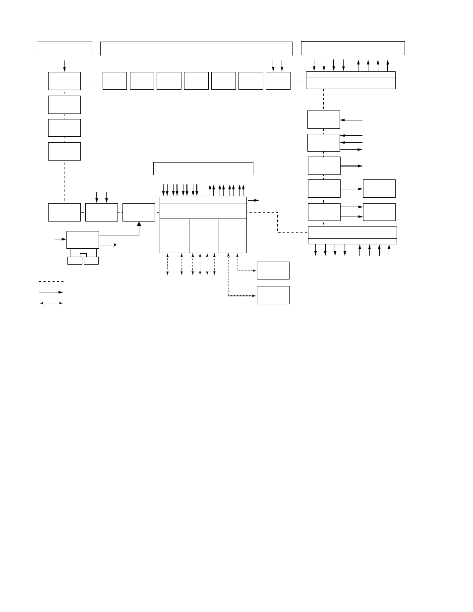
Figure 2-1—Block Diagram of Eagle Quantum Premier System