Eq25xxarm series agent release module – Det-Tronics EQP Fire and Gas Detection/Releasing System User Manual
Page 72
3-53
14.1
95-8533
EQ25XXARM SERIES AGENT RELEASE MODULE
Mounting
The device should be securely mounted to a vibration
free surface. (See “Specifications” in this manual for
device dimensions.)
Wiring
To ensure proper operating voltage for the output
device, the maximum wiring length from power source
to device must not exceed the values shown in Table
3-19 for automatic release applications or Table 3-20
for deluge and pre-action applications.
NOTE
For solenoids, this wire length includes both the
wiring from power supply to device, and the
wiring from device to solenoid.
See Figure 3-67 for identification of wiring terminals.
Terminals 1 to 4 —
Output terminals
Connect a single solenoid
between terminals 1 and 4.
Connect dual solenoids
between terminals 1 and 2,
and between terminals 3 and
4.
NOTE
For testing purposes, a load resistor of 1200 to
1500 ohms @ 1 watt can be placed across
terminals 1 and 4.
CAUTION!
DO NOT intermix different types of initiators in
release circuit.
Terminals 5 to 10 —
LO N s i g n a l i n g c i rc u i t
terminals
NOTE
Be sure to observe polarity when wiring the
LON.
5 — “A” side of signaling
circuit for COM 2
6 — “B” side of signaling
circuit for COM 2
7 and 8 —
s h i e l d
connections
9 — “A” side of signaling
circuit for COM 1
10 — “B” side of signaling
circuit for COM 1
Terminals 11 to 14 — 24 vdc power input
Connect module power
supply to terminals 12 and
13.
NOTE
If an auxiliary output supply is used for powering
solenoids, it should be connected to terminals 11
and 14.
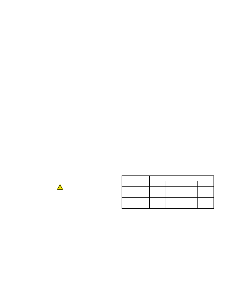
Table 3-19—Maximum Wiring Length for Automatic Release
Applications
*Fenwal Solenoid
**Ansul Solenoid
Device
Maximum Wire Length in Feet
12 AWG 14 AWG 16 AWG 18 AWG
890181*
150
100
60
895630*
150
100
60
897494*
190
120
75
570537**
3000
1900
1200
750