Det-Tronics EQP Fire and Gas Detection/Releasing System User Manual
Page 39
14.1
3-20
95-8533
The fiber optic link incorporates media converters to
convert from copper to fiber optic cable. The converter
must be located in the same cabinet as the controller
and cannot use ground fault monitoring. The approved
supported converters are shown in Table 3-9. The link
budget for the listed fiber optic converters is 10dB.
WARNINg
The fiber converters must be mounted inside the
same enclosure as the controllers to conform to NFPA
72.
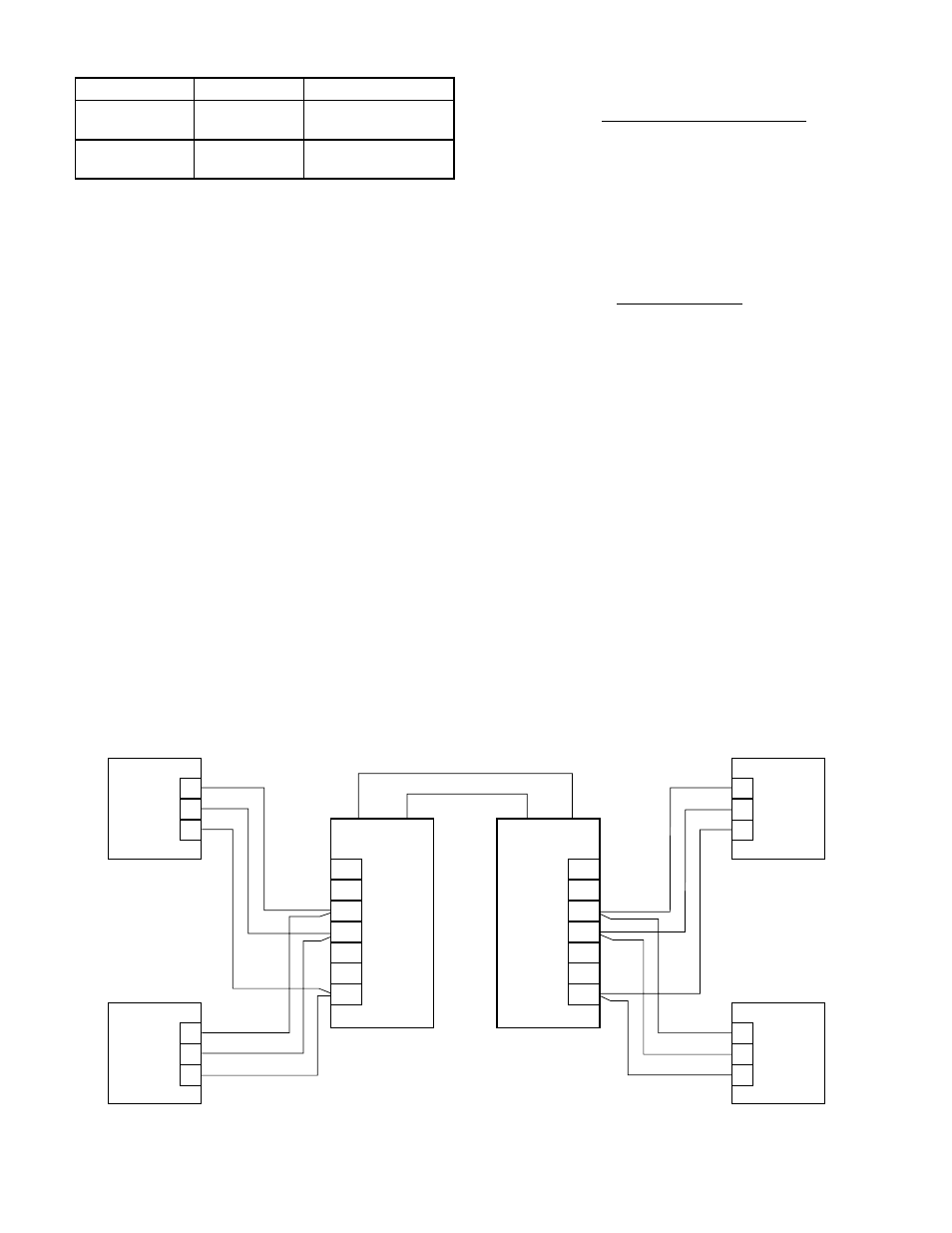
The media converter can be connected to either of the
EQP controller RS-485 communication ports (Port 1 or
Port 2). Figure 3-14 illustrates a typical Class B wiring
connection (single mode) between two EQP controllers
in a redundant configuration using Port 1. Note: If Port 2
is preferred, the optional serial board must be
purchased.
Figure 3-15 shows a typical Class X wiring connection
(single mode).
Figure 3-16 shows a typical Class X wiring connection
for Phoenix (multi mode).
For more information regarding selection and
installation of fiber optic media, please contact
Det-Tronics customer service.
Connector P11, Terminals 63, 64 & 65, Port 3–
RS-232 Modbus RTU Master/Slave
or S3 Configuration Port (Non-Isolated)
Configuration data downloaded into the controller
configures the serial interface transmission baud rate,
parity check and MODBUS device address for the
serial port. Software selectable baud rates are
9600,19200, 38400, 57600, 115200, and 230400.
Software selectable parity is None, Odd, and Even.
The controller uses 8 data bits with 1 stop bit.
Port Pinout (3-position terminal block)
63 — TXD
64 — RXD
65 — GND
Table 3-9—Approved Supported Media Converters for Fiber Optic Link
Figure 3-14—Controller to Controller NFPA 72 Approved Fiber Optic Link, Class B
PORT 1
RS-485
A
B
GND
56
55
54
PORT 1
RS-485
EQP CONTROLLER No. 1
56
55
54
A
B
GND
EQP CONTROLLER No. 2
PORT 1
RS-485
56
55
54
A
B
GND
EQP CONTROLLER No. 3
PORT 1
RS-485
56
55
54
A
B
GND
EQP CONTROLLER No. 4
T+
T–
R+D+
R–D–
Tx
Rx
GND
Tx
Rx
Moxa
TCF-142-S
T+
T–
R+D+
R–D–
Tx
Rx
GND
Rx
Tx
Moxa
TCF-142-S
FIBER OPTIC CABLE
B2328
SINGLE MODE
The maximum distance of a particular optic link given
the optical budget is calculated as:
Fiber Length = [Optical budget] – [Link Loss]
[Fiber Loss / km]
where link loss includes number of end connectors,
splices and safety margin.
Example: 10 db link budget
Cable Attenuation: 0.4 db / km
2 connectors: (1 each end) with 0.5 db ea.
Safety margin: 3.0 db max
Max. Distance = 10 – (2 x 0.5) – 3.0 = 15 km
0.4
Manufacturer
Model Number
Description
Moxa
(www.moxa.com)
TCF-142-S
RS-485 to Single-mode
Fiber Optical Converter
Phoenix Contact
PSI-MOS-
RS485W2/FO
RS-485 to Multi-mode
Fiber Optical Converter