Configuration – Det-Tronics EQP Fire and Gas Detection/Releasing System User Manual
Page 60
3-41
14.1
95-8533
Channel Connectors — Terminals 1 to 24
4-20 mA Input Devices
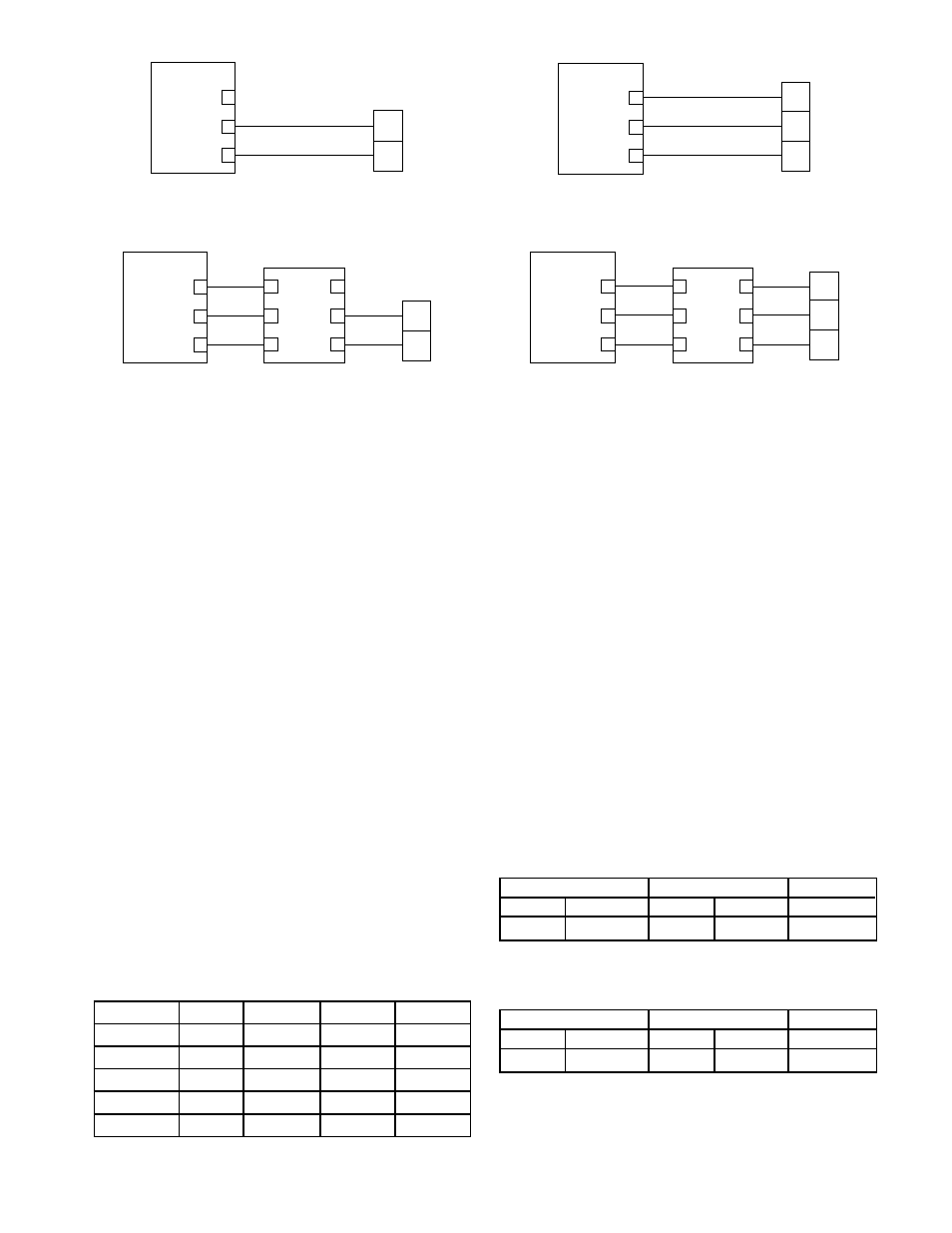
Connect external wiring to the appropriate terminals
on the analog input module terminal block. See
Figure 3-47 for an example of a 2-wire input. See
Figure 3-48 for a 2-wire input with HART interface
module. See Figure 3-49 for a 3-wire input, where the
transmitter must source a 4-20 mA signal. See Figure
3-50 for a 3-wire input with HART interface module.
Only channel 1 is shown in each diagram. The
information is typical for channels 2-8.
Analog Input Module Channels used as NFPA 72
Approved 4-20 mA Flame Detector Input
Configure the High Alarm setpoint at 19 mA via the S
3
configuration screen, and use the High Alarm to
trigger the Fire Alarm in S
3
logic. The AIM sends an
exception message for the High Alarm so there is no
delay in transmitting the Fire Alarm.
Fault indications and other status information must be
decoded in logic from the analog process variable. A
five second delay should be used to avoid indicating
an incorrect status condition while the analog value is
changing between two values. See Table 3-14.
CONFIGURATION
Setting Analog Input Module Network Address
One unique network address must be assigned to
each analog input module. The address is set by the
8 switch DIP assembly on the analog input module.
When using the switches located on the analog input
module, the address is binary coded and is the sum
of all switches placed in the “closed” position.
Each point of an analog input module has a tag
number and a descriptor for unique identification. A
tag number must include zone designation, which will
be shown on the controller's display when the point is
in alarm.
Det-Tronics S
3
Safety System Software is used for
device configuration. The following tables show the
minimum software/firmware releases:
+ SUPPLY A
4-20 MA IN B
COMMON C
CHANNEL 1
1
2
3
A2235
+
SIG
TRANSMITTER
+ SUPPLY A
4-20 MA IN B
COMMON C
CHANNEL 1
1
2
3
A2236
+
–
SIG
TRANSMITTER
+ SUPPLY A
4-20 MA IN B
COMMON C
CHANNEL 1
1
2
3
+ SUPPLY
4-20 MA IN
COMMON
HIM
1
4
2
5
3
6
A2238
+
SIG
TRANSMITTER
+ SUPPLY A
4-20 MA IN B
COMMON C
CHANNEL 1
1
2
3
A2239
+
–
SIG
TRANSMITTER
+ SUPPLY
4-20 MA IN
COMMON
HIM
1
4
2
5
3
6
Figure 3-47—Two-Wire Transmitter — Non-Isolated 4 to 20 mA
Current Output (Sourcing)
Figure 3-49—Three-Wire Transmitter — Non-Isolated 4 to 20 mA
Current Output (Sourcing)
Figure 3-48—Two-Wire Transmitter with HART Interface Module —
Non-Isolated 4 to 20 mA Current Output (Sourcing)
Figure 3-50—Three-Wire Transmitter with HART Interface Module —
Non-Isolated 4 to 20 mA Current Output (Sourcing)
Controller Firmware*
AIM
S3
Rev.
Version
Rev. Version
Version
B
3.06
B
1.02
2.9.1.1
*for part number 007606-002
For Gas Applications
Controller Firmware*
AIM
S3
Rev.
Version
Rev. Version
Version
C
5.52
D
1.07
4.0.0.0
*for part number 008983-001
For Flame Applications
Table 3-14—Analog Values (in mA) for Fault and Status Indications
when the AIM is Used as a 4-20 mA Flame Detector Input
Status
X3301/2
X5200
X9800
X2200
Fault
0-3.5
0-3.5
0-3.5
0-3.5
IR Pre-Alarm
7.0-9.0
UV Alarm
11.0-12.99
IR Alarm
13.0-14.99
Pre-Alarm
15.0-16.99 15.0-16.99 15.0-16.99