Det-Tronics EQP Fire and Gas Detection/Releasing System User Manual
Page 52
3-33
14.1
95-8533
The output can be configured for latching,
continuous, supervisory, trouble or timed response.
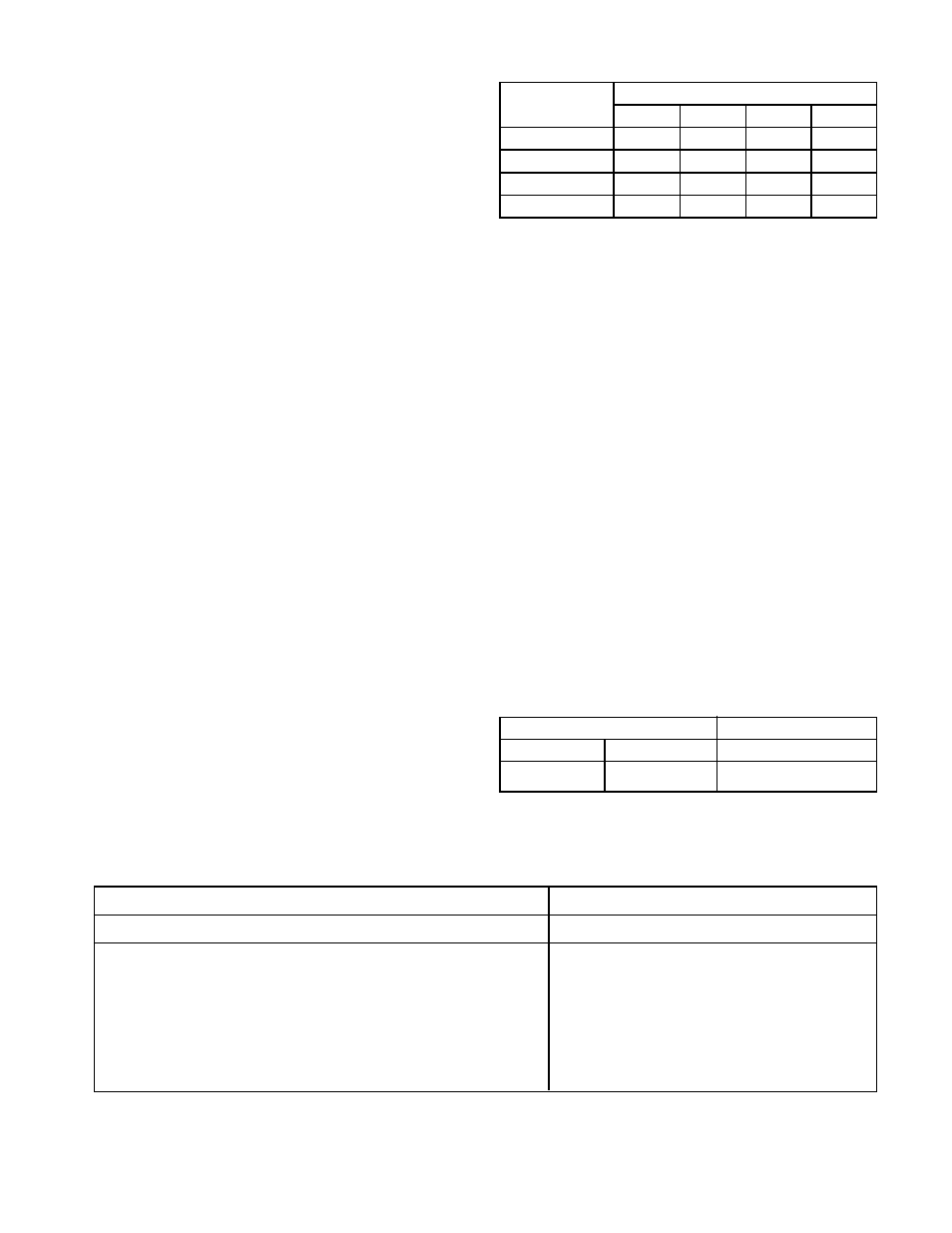
To ensure adequate operating voltage for the output
device, the maximum wiring length from the power
source to the output device must not exceed the
values shown in Table 3-10 for automatic release
applications. (For solenoids, this wire length includes
both the wiring from the power supply to the EDIO
module and the wiring from the module to the
solenoid.)
Supervised Output for Deluge and Pre-action
To ensure proper operating voltage, the input voltage
to the EDIO must be in the range from 21 to 30 vdc
and the maximum wiring length must not exceed the
values shown in Table 3-11 for deluge and pre-action
applications. Per FM Approval requirements, the
secondary power must provide capacity for a 90 hour
minimum standby operation followed by a minimum of
10 minutes of releasing and alarm operation. The
initiating device circuit(s) for use with the deluge
and pre-action system configuration must use
Class A wiring or be wired in conduit within 20 feet
from the EDIO.
NOTE
In EQP systems with EQP2120PS(–B) Power
Supplies, the secondary power is customer
supplied and must be accepted by the Authority
Having Jurisdiction (AHJ).
CONFIGURATION
Setting EDIO Network Address
One unique network address must be assigned to
each EDIO module. The address is set by the 8
switch DIP assembly on the EDIO module.
When using the switches located on the EDIO
module, the address is binary coded and is the sum
of all switches placed in the “closed” position.
Each discrete point of an EDIO module has a tag
number and a descriptor for unique identification. A
tag number must include zone designation, which will
be shown on the controller's display when the point is
in alarm.
Det-Tronics S
3
Safety System Software is used for
device configuration. The following shows the
minimum software/firmware releases:
Table 3-11—Maximum Wiring Length for FM Approved Solenoids for Deluge and Pre-Action Applications
Solenoids
Maximum Wire Length in Feet (Meters)
FM Solenoid Group Manufacturer
Model
12 AWG
14 AWG
16 AWG 18 AWG
B
ASCO
T8210A107
183 (56)
115 (35)
72 (22)
46 (14)
D
ASCO
8210G207
314 (96)
198 (60)
124 (38)
78 (24)
E
Skinner
73218BN4UNLVNOC111C2
331 (101)
208 (63)
131 (40)
82 (25)
F
Skinner
73212BN4TNLVNOC322C2
130 (40)
82 (25)
51 (16)
32 (10)
G
Skinner
71395SN2ENJ1NOH111C2
331 (101)
208 (63)
131 (40)
82 (25)
H
Viking
HV-274-0601
180 (55)
110 (34)
70 (21)
45(14)
Controller Firmware
S3
Revision
Version
Version
B
4.28
3.1.0.0
Table 3-10—Maximum Wire Length for Releasing Applications
*Fenwal Solenoid
**Ansul Solenoid
Device
Maximum Wire Length in Feet
12 AWG 14 AWG 16 AWG 18 AWG
890181*
150
100
60
895630*
150
100
60
897494*
190
120
75
570537**
3000
1900
1200
750