Ps n, Ps 1, Phoenix – Det-Tronics EQP Fire and Gas Detection/Releasing System User Manual
Page 47
14.1
3-28
95-8533
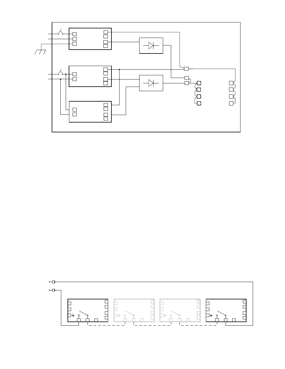
3. To ensure compliance with NFPA 72, primary and
secondary power supplies shall be monitored for
the presence of voltage at the point of connection
to the system. Connect the power supply unit for
preferred preventive function monitoring. Refer to
Figure 3-24 for an example of power supply
relays wired in series for power monitoring.
NOTE
Contacts are closed during normal operation.
The circuit shall be wired to an input on the EQP
system (EDIO or IDC). In Logic, the selected
input must be inverted and used to activate an
alarm trigger gate, which initiates a fault
message on the Controller and activates the fault
relay output.
No supervision is necessary, since the EDIO or
IDC module must be installed in the same
cabinet with EQP21X0PS and EQP2410PS.
For USCG Approved System monitoring details, refer to
Appendix D.
NOTE
For additional information, refer to the power
supply manufacturer’s documents provided with
the support documentation received with the
Eagle Quantum Premier system.
NRTL DISTRIBUTION CABINET
–
+
+
–
–
–
–
+
+
+
+
POWER DIST CKT #1
POWER DIST CKT #2
POWER DIST CKT #3
POWER DIST CKT #4
NOTES: 1. AC INPUT IS AUTO-SELECTABLE FOR 120–220 VAC, 60/50 Hz. BOTH AC AND DC INPUTS ARE CUSTOMER SUPPLIED.
2. PRIMARY SOURCE OF INPUT SUPPLY IS CONNECTED TO AC POWER SUPPLY AND SECONDARY SOURCE IS CONNECTED
TO DC CONVERTER.
3. A MAXIMUM OF 4 REDUNDANT PAIRS CAN BE CONNECTED TO INPUT AC/DC POWER.
4. THE SECONDARY SOURCE IS CONTINUOUSLY POWERED.
5. EQP CONTROLLER MUST BE INSTALLED IN THE SAME ENCLOSURE AS AC-DC POWER SUPPLY, DC-DC CONVERTER, AND
REDUNDANCY MODULE.
A2566
+
–
–
–
+
+
24 VDC
OUTPUT
EQP2410PS(–P) CONVERTER
DC POWER
See Notes 1 & 2
L
N
–
–
+
+
24 VDC
OUTPUT
EQP2120PS(–X) POWER SUPPLY
AC POWER
See Notes 1 & 2
IN
OUT
REDUNDANCY
MODULE
1
IN
OUT
REDUNDANCY
MODULE
1
2
CB
CB
G
+
–
–
–
+
+
24 VDC
OUTPUT
EQP2410PS(–P) CONVERTER
Figure 3-23C—Wiring Connections for One EQP2120PS(-X) Power Supply with Two EQP2410PS(-P) Converters (Typical)
To EDIO or IDC
L
N
–
–
+
+
DC
OK
13
14
PS n
PHOENIX
QUINT-PS
L
N
–
–
+
+
DC
OK
13
14
PS 1
PHOENIX
QUINT-PS
L
N
–
–
+
+
DC
OK
13
14
PS
PHOENIX
QUINT-PS
L
N
–
–
+
+
DC
OK
13
14
PS
PHOENIX
QUINT-PS
D2438
Figure 3-24—Power Supply and Converter Relays Wired in Series for Trouble Monitoring (up to 16 Power Supplies/Converters)