Det-Tronics EQP Fire and Gas Detection/Releasing System User Manual
Page 67
14.1
3-48
95-8533
CAUTION!
The sensor threads can be coated with an
appropriate grease to ease installation. Also
lubricate the cover threads. (See “Ordering
Information” for part number of recommended
lubricant.)
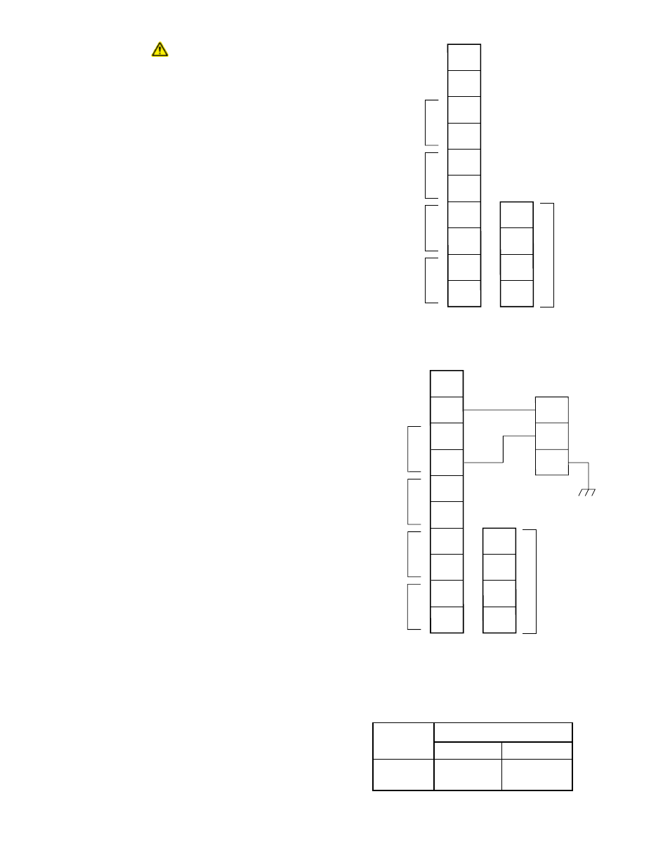
Connect the external wiring to the appropriate
terminals on the DCU terminal wiring board. Refer to
Figure 3-61 for terminal identification. See Figure 3-62
for an example of a Det-Tronics electrochemical
sensor connected to a DCU.
Attach the communication module to the standoffs as
shown in Figure 3-60. Connect the ribbon cable from
the terminal wiring board to the communication
module.
Set the address for the device. Refer to “Setting
Device Network Addresses” for complete information
regarding the switch setting procedure.
Check the wiring to ensure proper connections, then
pour the conduit seals and allow them to dry (if
conduit is being used).
NOTE
Before placing the cover back on the enclosure
following completion of assembly and wiring,
inspect the enclosure O-ring to be sure that it is
in good condition and properly installed.
Lubricate the O-ring and the threads of the cover
with a thin coat of an appropriate grease to ease
installation. Refer to the “Ordering Information”
section for the part number of the recommended
grease (available from Detector Electronics). If
the installation uses catalytic type combustible
gas sensors, it is imperative that lubricants
containing silicone not be used, since they will
cause irreversible damage to the sensor. Place
the cover on the enclosure. Tighten only until
snug. Do not over tighten.
Sensor Separation for DCU with H2S and O2
Sensors
Since the transmitter for the electrochemical sensor is
already mounted within the sensor housing, simply
mount the entire sensor assembly to the sensor
separation kit junction box and wire it to terminals 2
and 4 inside the DCU, the same as a regular (without
sensor separation) installation. Connect the shield to
the ground terminal in the DCU junction box.
Refer to Table 3-17 for separation distance limitations
for H2S and O2 sensors.
1
2
3
4
5
6
7
8
9
10
14
13
12
11
–
–
+
+
24 VDC
POINTWATCH CALIBRATE
4 TO 20 MA IN
–
+
A
B
A
B
SENSOR POWER
COM 2
COM SHIELD
COM 1
A1726
Figure 3-61—Wiring Configuration for DCU
1
2
3
4
5
6
7
8
9
10
BLACK
RED
GREEN
DCU
H2S/TOXIC/O2
14
13
12
11
–
–
+
+
24 VDC
POINTWATCH CALIBRATE
4 TO 20 MA IN
–
+
A
B
A
B
SENSOR POWER
COM 2
COM SHIELD
COM 1
A1875
Figure 3-62—Electrochemical Sensor Connected to DCU
T0020A
Wire Size
Maximum Wiring Distance
(AWG)
Feet
Meters
18
5700
1750
16
9000
2800
Table 3-17
Maximum Separation Distances — Electrochemical Sensor to DCU