Det-Tronics EQP Fire and Gas Detection/Releasing System User Manual
Page 62
3-43
14.1
95-8533
Channels 1 to 3, Terminals 1 to 9
Channels 1 to 3 Inputs
Refer to individual wiring configurations for terminal
descriptions. Only channel 1 is shown in each
diagram. The information is typical for channels 1-3.
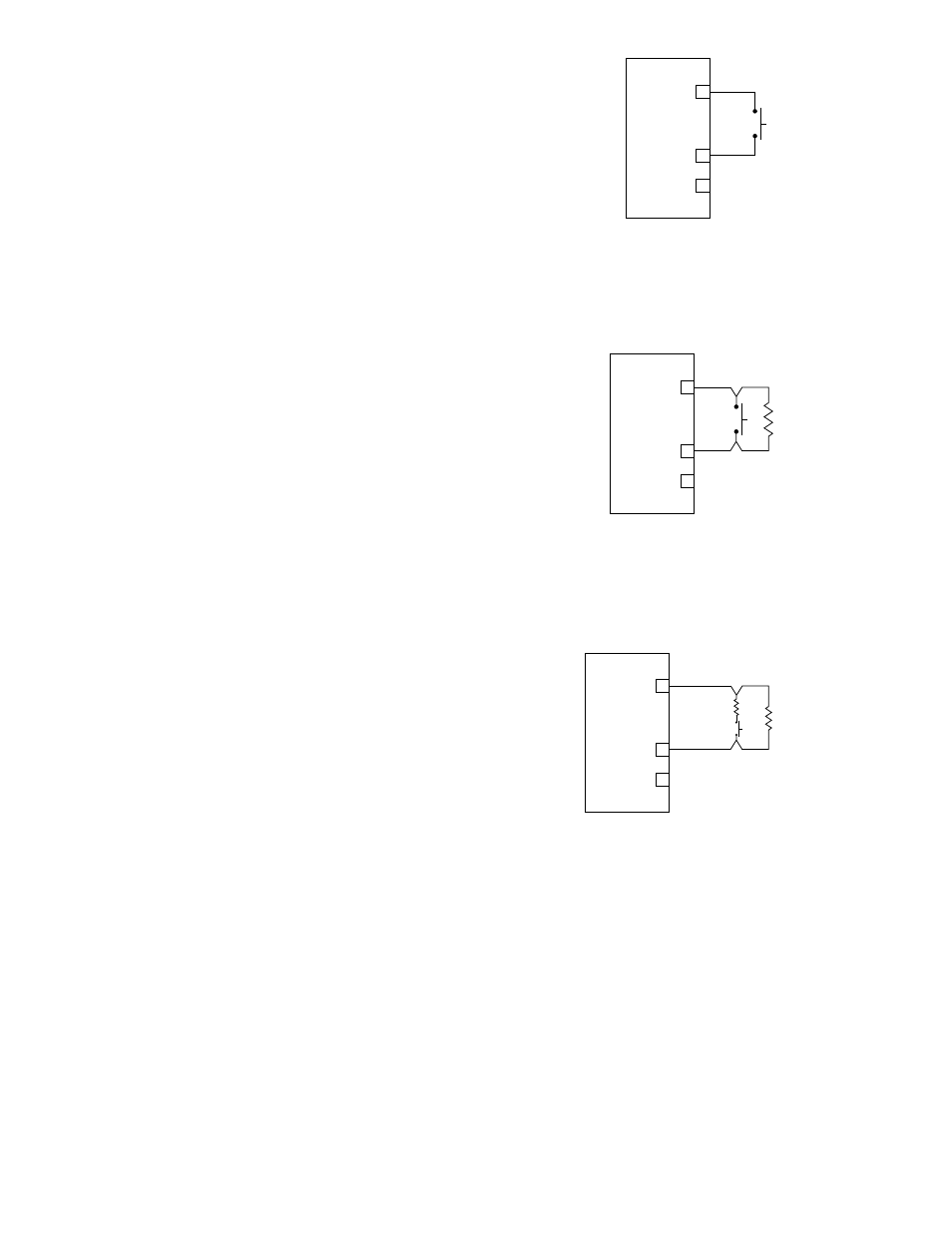
Unsupervised Input
Connect external system wiring to the appropriate
terminals on the terminal block. See Figure 3-52.
The input to the IPM consists of one or more normally
open switches. An EOL resistor is not required.
No connection should be made to “+ Supply”
terminal.
NOTE
Unsupervised inputs are not recommended for
fire alarm applications.
Supervised Input (IDC) Open Circuit Supervision
(Two State – Open and Switch Closure)
Class B
Connect external system wiring to the appropriate
terminals on the terminal block. See Figure 3-53.
The input to the IPM consists of one or more normally
open switches, with a 10 K ohm, 1/4 watt EOL resistor
in parallel across the last switch.
Make no connection to “+ Supply” terminal.
Supervised Input (IDCSC) Open and Short Circuit
Supervision
(Three state – open, switch closure, and short)
Class B
Connect external system wiring to the appropriate
terminals on the terminal block. See Figure 3-54.
The input to the IPM consists of a normally open
switch, with a 10 K ohm, 1/4 watt EOL resistor in
parallel across the switch, and a 3.3 K ohm, 1/4 watt
resistor in series with the switch.
Make no connection to “+ Supply” terminal.
+ SUPPLY A
IN– / OUT+ B
COMMON C
1
2
3
B2090
+ SUPPLY A
IN– / OUT+ B
COMMON C
1
2
3
EOL
RESISTOR
10 K
Ω
B2091
Figure 3-52—Unsupervised Input Configuration
Figure 3-53—Supervised Input Configuration
+ SUPPLY A
IN– / OUT+ B
COMMON C
1
2
3
EOL
RESISTOR
10 K
Ω
INLINE
RESISTOR
3.3 K
Ω
B2092
Figure 3-54—Supervised Input Configuration (Opens and Shorts)