Configuration – Det-Tronics EQP Fire and Gas Detection/Releasing System User Manual
Page 64
3-45
14.1
95-8533
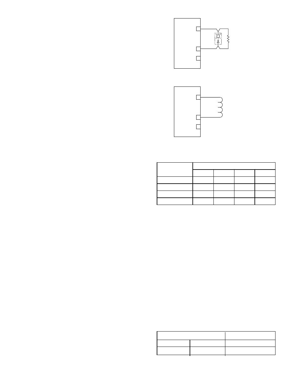
Supervised Output
Notification Supervised for Open & Short Circuits
Connect external system wiring to the appropriate
terminals on the terminal block. See Figure 3-58.
The output of the IPM supervises the notification circuit
by reversing the polarity of the monitoring circuit.
Polarity must be observed when connecting the
notification device. It is essential to utilize a notification
device approved for fire alarm notification. These
devices are polarized and would not require the use of
an external diode for the supervision of the circuit. Wire
one or more notification devices to the output, with a 10
K ohm, 1/4 watt EOL resistor in parallel across the last
device.
No connection should be made to “+ Supply” terminal.
Each output channel is individually activated for
response pattern:
– supervisory
– continuous output
– 60 beats per minute
– 120 beats per minute
– temporal
– trouble.
Channels 7 and 8, Terminals 19 to 24
Supervised Output Agent Release
Connect external system wiring to the appropriate
terminals on the terminal block. See Figure 3-59.
No connection should be made to “+ Supply” terminal.
The output of the IPM supervises the releasing circuit via
the coil of the releasing solenoid. It is essential to utilize
a releasing device approved for use with this output
module. This type of output does not require the use of
EOL resistors or diodes to supervise the circuit.
The output can be configured for continuous or timed
response.
To ensure adequate operating voltage for the output
device, the maximum wiring length from the power
source to the output device must not exceed the values
shown in Table 3-15 for automatic release applications
or Table 3-16 for deluge and pre-action applications.
For solenoids, this wire length includes both the wiring
from the power supply to the IPM and the wiring from the
module to the solenoid.
NOTE
For FM system approval listing, pre-action and
deluge applications require that only FM approved
deluge valves can be wired into the IPM module.
Remember that the valves must utilize 24 vdc and
must not exceed 2 amperes current draw.
CONFIGURATION
Setting Module Network Address
One unique network address must be assigned to
each intelligent protection module. The address is set
by the 8 switch DIP assembly on the module. The
address is binary coded and is the sum of all
switches placed in the “closed” position.
Each discrete point of an intelligent protection module
has a tag number and a descriptor for identification.
Det-Tronics S
3
Safety System Software is used for
device configuration. The following shows the
minimum software/firmware releases:
+ SUPPLY A
IN– / OUT+ B
COMMON C
16
17
18
EOL
RESISTOR
10 K
Ω
B2094
Figure 3-58—CH-6: Supervised Output Configuration (Notification)
+ SUPPLY A
IN– / OUT+ B
COMMON C
19
20
21
NOTE: SHUNT/FLYBACK DIODES DO NOT NEED
TO BE INSTALLED ON THE FIELD DEVICE.
CIRCUIT PROTECTION IS PROVIDED
WITHIN THE IPM.
Figure 3-59—CH-7&8: Supervised Output Configuration (Agent Release)
Controller Firmware
S3
Revision
Version
Version
B
3.06
2.9.0.1
Table 3-15—Maximum Wire Length for Releasing Applications
*Fenwal Solenoid
**Ansul Solenoid
Device
Maximum Wire Length in Feet
12 AWG 14 AWG 16 AWG 18 AWG
890181*
150
100
60
895630*
150
100
60
897494*
190
120
75
570537**
3000
1900
1200
750