Det-Tronics EQP Fire and Gas Detection/Releasing System User Manual
Page 56
3-37
14.1
95-8533
Supervised Output for Automatic Release
Supervised Output for Open Circuits
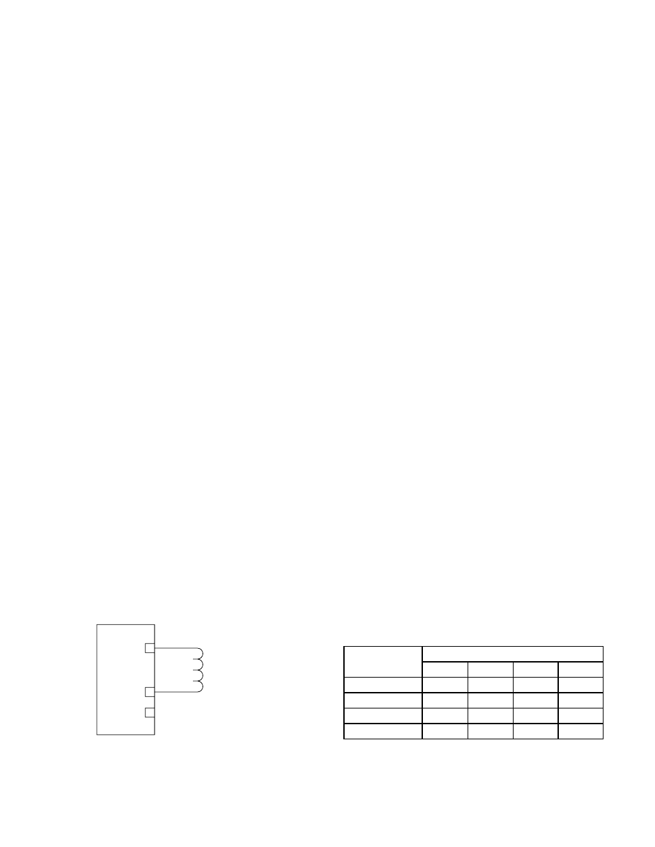
Connect external wiring to the appropriate terminals
on the DCIO terminal block. See Figure 3-43.
Wire one or more releasing devices to the module
output.
NOTE
Make no connection to the “+ Supply” terminal.
The output of the DCIO module supervises the
releasing circuit via the coil of the releasing solenoid.
It is essential to use a releasing device approved for
use with this output module.
NOTE
This type of output does not require the use of
EOL resistors or diodes to supervise the circuit.
The output can be configured for latching, continuous
or timed response.
To ensure proper operating voltage, the maximum
wiring length from the power source to the DCIO
module must not exceed the values shown in Table
3-12 for automatic release applications.
NOTE
For solenoids, this wire length includes both the
wiring from the power supply to the DCIO
module and the wiring from the module to the
solenoid.
Supervised Output for Deluge and Pre-action
Connect external wiring to the appropriate terminals
on the DCIO terminal block. See Figure 3-43.
The output of the DCIO module supervises the
releasing circuit via the coil of the releasing solenoid.
It is essential to use a releasing device approved for
use with this output module.
NOTE
This type of output does not require the use of
EOL resistors or diodes to supervise the circuit.
NOTE
Fo r n ew o r re t ro fi t i n s ta l l a t i o n s , a ny
manufacturer’s non-water based agent release
valves can be wired into the outputs of the ARM
or DCIO modules as long as the devices utilize
24 vdc and do not exceed 2 amperes current
draw.
NOTE
For FM system approval listing, pre-action and
deluge applications require that only FM
approved deluge valves can be wired into the
ARM or DCIO modules. Table 3-13 lists the
supported solenoid groups. Remember that the
valves must utilize 24 vdc and must not exceed
2 amperes current draw.
The output can be configured for latching, continuous
or timed response.
To ensure proper operating voltage, the input voltage
to the DCIO must be in the range from 21 to 30 vdc
and the maximum wiring length must not exceed the
values shown in Table 3-13 for deluge and pre-action
applications. Per FM Approval requirements, the
secondary power must provide capacity for a 90 hour
minimum standby operation followed by a minimum of
10 minutes of releasing and alarm operation. For
initiating device circuit(s) for use with the deluge
and pre-action system configuration, an Enhanced
Discrete Input/Output Module (EDIO) must be
used.
+ SUPPLY A
IN– / OUT+ B
COMMON C
1
2
3
NOTE: SHUNT/FLYBACK DIODES DO NOT NEED
TO BE INSTALLED ON THE FIELD DEVICE.
CIRCUIT PROTECTION IS PROVIDED
WITHIN THE DCIO.
A2323
Figure 3-43—Supervised Output Configuration (Automatic Release)
Table 3-12—Maximum Wire Length for Automatic Releasing
Applications
*Fenwal Solenoid
**Ansul Solenoid
Device
Maximum Wire Length in Feet
12 AWG 14 AWG 16 AWG 18 AWG
890181*
150
100
60
895630*
150
100
60
897494*
190
120
75
570537**
3000
1900
1200
750