Eq2220gfm ground fault monitor, Field devices – Det-Tronics EQP Fire and Gas Detection/Releasing System User Manual
Page 13
14.1
95-8533
2-7
Communication wire segment lengths are
dependant upon physical and electrical
characteristics of the cable. Refer to the
installation section for Lon cable wire
information.
no more than six network extenders may be
used on the communication loop.
When a network extender is installed in the
communication loop, up to 40 field devices can
be installed per network segment. the network
segment is the wiring segment between two
network extenders or between a network
extender and a controller.
EQ21xxps series power supplies and
EQ2100psm power supply monitor
The Power Supply, Power Supply Monitor, and backup
batteries are used to provide power to the system.
The power supply monitor communicates trouble
conditions to the Controller. Monitored status
conditions include: power supply failure, loss of AC
power, loss of battery power, power ground fault, AC
and DC voltage (hi/low level), and backup battery
current charge levels.
The Power Supply provides main and backup power
to the EQP System. The device includes many
features such as voltage regulation, high efficiency,
and high power factor.
An equalize switch is located on the front panel of the
charger for manual activation, or a multi-mode
electronic timer can be used for automatic activation.
Steady state output voltage remains within +/– 1/2%
of the setting from no load to full load for AC input
voltages within +/– 10% of the nominal input voltage.
EQp21XXps(–X) power supplies and
EQp2410ps(–p) Converter
The Power Supplies and Converter provide main and
backup power to the EQP System in ordinary and
marine applications. Refer to Section 3 of this manual
for complete information.
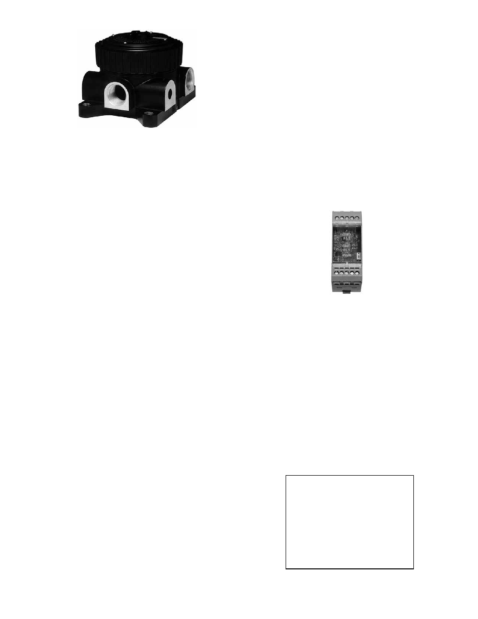
EQ2220GFm Ground Fault monitor
The EQ2220GFM Ground Fault Monitor (see Figure
2-8) provides ground fault monitoring in a system that
includes a floating 24 Vdc power source. The device
detects ground fault conditions on +/– power and all
secondary I/O circuits. A positive or negative ground
fault condition is indicated immediately by local
LEDs, and by a relay contact after a 10 second time
delay. The ground fault monitor is intended to be
mounted in the same enclosure as the controller.
FiELD DEViCEs
Flame Detectors
For flame detector installation, operation,
maintenance, specifications and ordering information,
refer to Table 2-5.
For information regarding USCG Approval of the
X3301 Flame Detector, refer to Appendix D.
note
existing eagle Quantum field devices such as
eQ22xxUV and eQ22xxUVIR are supported by the
eagle Quantum Premier system (not FM Approved).
Table 2-5—Flame Detector Manuals
Detector
manual number
X3301 95-8527
X3301A
95-8527 & 95-8534
X3302 95-8576
X5200 95-8546
X2200 95-8549
X9800 95-8554
UVHT 95-8570
Figure 2-8—Ground Fault Monitor
Figure 2-7—Eagle Quantum Premier Network Extender