Wiring, Tronics, Eagle quantum premier safety system controller – Det-Tronics EQP Fire and Gas Detection/Releasing System User Manual
Page 34
3-15
14.1
95-8533
WIRING
Power Wiring
CAUTION!
Input voltage at the Controller must be 18 vdc
minimum to ensure proper operation.
It is important to consider both the wire gauge and the
distance from the Controller to the power supply. As
the distance between the Controller and the power
supply increases, so must the diameter of the power
wiring in order to maintain a minimum of 18 vdc at the
Controller.
IMPORTANT!
To ensure proper operation of devices, the
voltage input to the device (measured at the
device) must be within the range indicated for
that device in the "Specifications" section of this
manual.
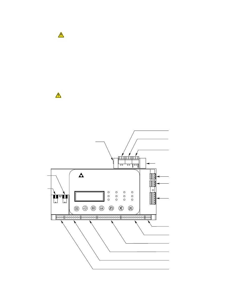
Electrical Connections
Figure 3-8 shows the location of wiring connectors on
the Controller module. Figure 3-9 identifies individual
terminals.
Connector P1, Terminals 1 to 4 —
24 vdc Input Power
Connect the power supply to terminals 1 and 2 of the
Controller. Terminals 3 and 4 must also be connected
to power.
When controller and power supplies are installed in
separate NRTL cabinets, two power cables from two
distribution circuits are required, so that if one is lost,
the controller will continue to operate and signal a
trouble condition. The power circuit must be
protected against physical damage.
Shields on power cables must be connected to
chassis ground (earth).
P9: TERMINALS 57 TO 59
RS-232 S3 CONFIGURATION PORT
P11: TERMINALS 63 TO 65 – PORT 3
RS-232 MODBUS RTU MASTER/SLAVE
OR S3 CONFIGURATION
P12: TERMINALS 66 TO 68 – PORT 4
RS-232 MODBUS RTU MASTER/SLAVE
P10: TERMINALS 60 TO 62 - PORT 2
RS-485 MODBUS RTU MASTER/SLAVE
P8: TERMINALS 54 TO 56 - PORT 1
RS-485 MODBUS RTU MASTER/SLAVE
P7: TERMINALS 48 TO 53
LON CONNECTIONS
P6: TERMINALS 45 TO 47
FAULT RELAY (NC CONTACT)
P5: TERMINALS 33 TO 44
RELAYS 5 TO 8
P4: TERMINALS 21 TO 32
RELAYS 1 TO 4
P3: TERMINALS 13 TO 20
DIGITAL INPUTS 5 TO 8
P2: TERMINALS 5 TO 12
DIGITAL INPUTS 1 TO 4
P1: TERMINALS 1 TO 4
24 VDC INPUT POWER
E2105
EAGLE QUANTUM PREMIER
Safety System Controller
Fire Alarm
Inhibit
Power
Supr
High Gas
Trouble
Cntrl Flt
Lon Fault
Low Gas
Ack
Silence
Out Inhibit
Eagle Quantum Premier
Time & Date
Cancel
Enter
Next
Previous
Reset
Acknowledge Silence
1
4
60
62
63
65
66
68
5
12 13
20 21
32 33
44 45
47
48
53
54
56
57
59
CONTROLNET
BNC CONNECTOR A
CONTROLNET
BNC CONNECTOR B
P13: HIGH SPEED SERIAL LINK (HSSL)
RS-232 (REDUNDANCY ONLY)
DET
-
TRONICS
®
SERIAL COMMUNICATION BOARD
(OPTIONAL)
Figure 3-8—Location of Wiring Terminals on EQP Controller