Multiple wiring faults, Major component descriptions, System controller – Det-Tronics EQP Fire and Gas Detection/Releasing System User Manual
Page 11
14.1
95-8533
2-5
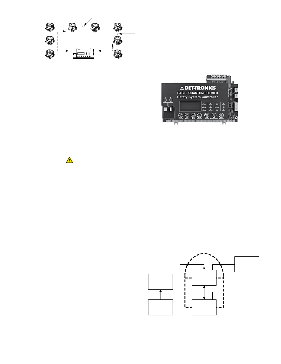
muLtipLE WiRinG FauLts
In the event of multiple wiring faults on the LON, the
devices between the faults will continue to function,
but the faults will prevent them from communicating
with the Controller. See Figure 2-4. In this example,
nodes 1 to 4 communicate using one Controller port
(path A) and nodes 7 and 8 use the other Controller
port (path B). Nodes 5 and 6 are unable to report to
the Controller because they are isolated by the two
wiring faults. If a device is prevented from
communicating with the Controller, the text display on
the Controller will show the message “Device Offline”.
impoRtant!
Since it is impossible to predict where a network
fault might occur or exactly what effect it will
have on actual system operation, it is important
to diagnose and repair any fault as soon as
possible after it is detected to ensure continuous,
uninterrupted system operation.
mAJor component DeScrIptIonS
The system has three (3) main component groups —
the System Controller, LON (Local Operating
Network), and Intelligent Field Devices.
sYstEm ContRoLLER
The Controller (see Figure 2-5) performs all
communication, command, and control functions for
the system. The Controller supports both “Static” and
“Programmable” logic. Other features include:
• Redundant controller capability
• User pushbutton controls (reset, acknowledge, etc.)
• “Real time” system clock
• Internal alarm sounder
• Vacuum fluorescent text based display that shows
current system status
• 8 programmable unsupervised inputs
• 8 programmable unsupervised relay outputs
• RS-485 Modbus RTU communication interface that
supports coils, discrete inputs, and holding
registers
• Optional ControlNet communication board that
supports redundant communication channels.
• Optional Serial Interface Board (required for
controller redundancy).
Figure 2-5—System Controller
Controller Redundancy
The EQP controllers can be configured as a redundant
pair. See Figure 2-6. The redundancy scheme is a hot
standby system that offers the following primary
features:
• Automatic configuration of the standby controller
• Bumpless transfer
• Forced and automatic switchover
• No downtime on controller replacement
• Automatic synchronization between controllers
• Increased system availability
Figure 2-4—Communication over LON with Multiple Wiring Faults
D1853
NODE 1
NODE 8
NODE 3
NODE 6
NODE 2
NODE 7
NODE 4
NODE 5
PATH A
PATH B
WIRING FAULTS
EQP
CONTROLLER
EAGLE QUANTUM PREMIER
Safety System Controller
Fire Alarm
Inhibit
Power
Supr
High Gas
Trouble
Cntrl Flt
Lon Fault
Low Gas
Ack
Silence
Out Inhibit
Eagle Quantum Premier
Time & Date
Cancel
Enter
Next
Previous
Reset
Acknowledge Silence
DET
-
TRONICS
®
LON
S3
CONFIGURATION
SOFTWARE
ONE PROJECT FILE
LOADED TO
CONTROLLER A
CONTROLLER A
LON ADDRESS 1
CONTROLLER B
LON ADDRESS 2
DCS/PLC/HMI
HIGH SPEED
RS-232
SERIAL LINK
RS-232
SERIAL LINK
MODBUS
RS-485
A2275
Figure 2-6— Block Diagram of EQP System
with Redundant Controllers