High speed serial link (hssl), Lon wiring, Wiring – Det-Tronics EQP Fire and Gas Detection/Releasing System User Manual
Page 41: Mounting, Enclosure requirements, Eq3xxx redundant controller installation
14.1
3-22
95-8533
Connector P12, Terminals 66, 67 & 68, Port 4–
RS-232 Modbus RTU Master/Slave (Non-Isolated)
Configuration data downloaded into the controller
configures the serial interface transmission baud rate,
parity check and MODBUS device address for the
serial port. Software selectable baud rates are
9600,19200, 38400, 57600, 115200, and 230400.
Software selectable parity is None, Odd, and Even.
The controller uses 8 data bits with 1 stop bit.
Port Pinout (3-position terminal block)
66 — TXD
67 — RXD
68 — GND
Connector P13 —
RS-232 High Speed Serial Port
This port is dedicated to inter-controller connection
required for redundancy, and is not available for any
other use. This port is automatically configured.
CONFIGURATION
Software Defined Addresses
Det-Tronics Safety System Software (S3) is
programmed with the addresses that are assigned to
the controller when the configuration file is
downloaded into the controller. Addresses define and
configure the Controller’s LON address, Modbus slave
address, and the ControlNet option board address.
Each device on the LON must be assigned a unique
tag number. This tag number must include zone
designation, which will be shown on the Controller's
display when the device is in alarm.
EQ3XXX REDUNDANT CONTROLLER
INSTALLATION
The redundant controllers must be purchased with the
following options for correct installation:
• Serial board
• High-speed serial cable
• LON termination modules (2).
ENCLOSURE REQUIREMENTS
The redundant controllers must be located next to
each other in the same enclosure (4 ft. interconnecting
cable).
MOUNTING
The controllers are designed for direct panel mounting
or DIN rail mounting. See “Specifications” section of
this manual for mounting dimensions.
WIRING
The redundant controllers are wired the same as a
simplex controller except for the LON wiring and the
dedicated high-speed serial link, which are defined
below. Refer to EQ3XXX Controller Installation for
general installation details.
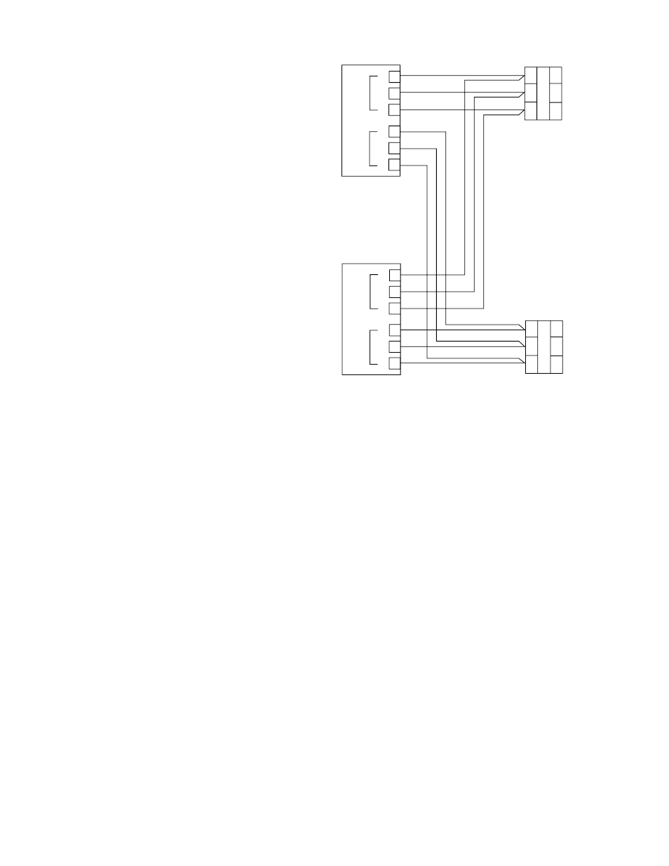
LON WIRING
The LON must be connected to both redundant
controllers to ensure correct operation. Two LON
Termination Modules are required for the installation
as shown in Figure 3-17.
HIGH SPEED SERIAL LINK (HSSL)
The redundant controllers are connected together by
a dedicated high-speed serial link. This link is a pre-
fabricated cable that has a custom connector for ease
of use. Redundant controllers are automatically
addressed with the HSSL cable. One end of the
cable is labeled Primary. The primary controller takes
address 1, while the secondary controller is address
2. The significance this has for the user is that the
primary is the default master when both controllers
are powered-up at the same time.
C2274
A
B
S
COM 2
A
B
S
COM 1
EQP
CONTROLLER
53
52
51
50
49
48
A
B
S
COM 2
A
B
S
COM 1
EQP
CONTROLLER
53
52
51
50
49
48
NOTE: LON TERMINATION JUMPERS P25 AND P26 (SEE FIGURE 3-12)
MUST BE IN POSITION 2 AND 3 FOR REDUNDANT CONFIGURATION
(ON BOTH CONTROLLERS).
LON
TERMINATION
MODULE
A
3
2
1
6
5
4
B
S
COM 2 TO
FIELD
DEVICES
LON
TERMINATION
MODULE
A
3
2
1
6
5
4
B
S
COM 1 TO
FIELD
DEVICES
Figure 3-17— LON Connection for Redundant EQP Controllers