Det-Tronics EQP Fire and Gas Detection/Releasing System User Manual
Page 75
14.1
3-56
95-8533
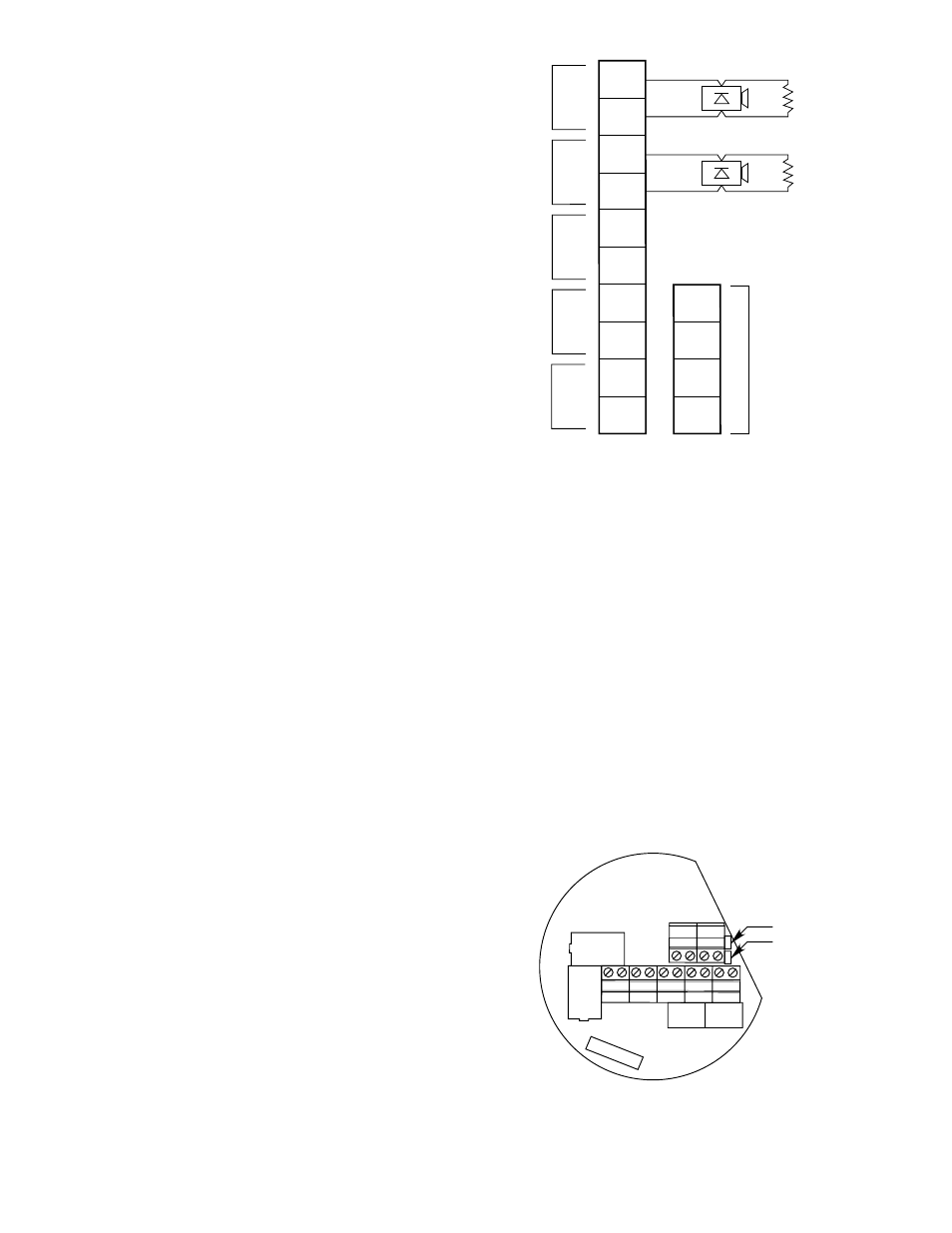
Terminals 1 to 4 —
Output terminals
Connect the first output
device between terminals 1
and 2, and the second
between terminals 3 and 4.
NOTE
Polarity shown in Figure 3-69 is for monitoring
condition; polarity is reversed when activated.
Each circuit must have a 10
kohm EOL resistor.
Terminals 5 to 10 — LON signaling circuit
terminals
Be sure to observe polarity
when wiring the LON.
5 — “A” side of signaling
circuit for COM 2
6 — “B” side of signaling
circuit for COM 2
7 and 8 —
s h i e l d
connections
9 — “A” side of signaling
circuit for COM 1
10 — “B” side of signaling
circuit for COM 1
Terminals 11 to 14 — 24 vdc power input
Connect the module power
supply to terminals 12 and
13. If an auxiliary output
supply is used for powering
signaling devices, it should
be connected to terminals 11
and 14.
Jumpers
Terminals 13 and 14 are connected by jumper JP2
and terminals 11 and 12 are connected by jumper
JP1. These two jumpers (JP1 and JP2) must be cut if
an auxiliary output power supply is being used. (See
Figure 3-70) for jumper locations.
Address Setting
Set device network address. (See “Setting Device
Network Addresses” in this section.)
9 10
7 8
5 6
3 4
1 2
1314
1112
JP1
JP2
B1903
Figure 3-70—Signal Audible Module Wiring Terminals and Jumpers
1
2
3
4
5
6
7
8
9
10
14
13
12
11
–
–
+
+
24 VDC
+
–
+
–
A
B
A
B
OUTPUT 1
*
OUTPUT 2
*
COM 2
COM SHIELD
COM 1
*
POLARITY SHOWN IS FOR MONITORING CONDITION,
POLARITY IS REVERSED WHEN ACTIVATED.
NOTE:
TERMINALS 12 AND 13 ARE FOR MODULE POWER SUPPLY.
TERMINALS 11 AND 14 ARE FOR AUXILIARY OUTPUT POWER SUPPLY.
JUMPERS JP1 AND JP2 MUST BE REMOVED IF AN AUXILIARY POWER SUPPLY IS USED.
B1901
10K EOL
10K EOL
Figure 3-69—Wiring Configuration for Signal Audible Module