6 beep generator, Refer to, Figure 28 – Cirrus Logic CS42L56 User Manual
Page 44: Cs42l56
44
DS851F2
CS42L56
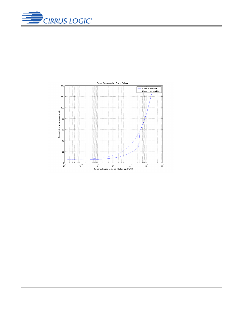
When the rail voltages are set to VCP, the amplifiers will operate in their least efficient mode. When the
rail voltages are held at ±VCP/2, the amplifiers will operate in their most efficient mode, but will be clipped
if required to amplify a full-scale signal. Note: The ±VCP/2 curve ends at the point at which the output of
the amplifiers reaches 10% THD+N.
The benefit of Bi-Modal Class H is shown in the solid trace on the graph. At lower output levels, the am-
plifiers operate on the ±VCP/2 curve. At higher output levels, they operate on the ±VCP curve. The dura-
tion the amplifiers will operate on either of the two curves (±VCP/2 or ±VCP) depends on both the content
and the output level of the program material being amplified. The highest efficiency operation will result
from maintaining an output level that is close to, but not exceeding, the clip threshold of the ±VCP/2 curve.
4.6
Beep Generator
The Beep Generator generates audio frequencies across approximately two octave major scales. It offers
three modes of operation: Continuous, multiple, and single (one-shot) beeps. Sixteen On and eight Off times
are available.
It should be noted that the beep is generated before the limiter and may affect desired limiting performance.
If the limiter function is used, it may be necessary to set the beep volume sufficiently below the threshold to
prevent the peak detect from triggering. Since the master volume control, MSTxVOL[7:0], will affect the
beep volume, the DAC volume may alternatively be controlled using the PMIXxVOL[6:0] bits.
Figure 28. Class H Power to Load vs. Power from VCP Supply - 16
All Supplies= 1.8 V
R
L
= 16