Figure 20. analog output stage, 5 class h amplifier, Figure 20.analog output stage – Cirrus Logic CS42L56 User Manual
Page 38: Cs42l56
38
DS851F2
CS42L56
4.5
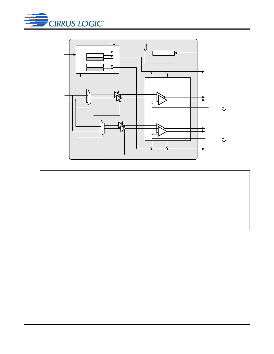
Class H Amplifier
The CS42L56 headphone and line output amplifiers use a Cirrus Logic patented Bi-Modal Class H technol-
ogy. This technology maximizes operating efficiency of the typical Class AB amplifier while maintaining high
performance. In a Class H amplifier design, the rail voltages supplied to the amplifier vary with the needs of
the music passage that is being amplified. This prevents unnecessarily wasting energy during low power
passages of program material or when the program material is played back at a low volume level.
The central component of the Bi-Modal Class H technology found in the CS42L56 is the internal charge
pump, which creates the rail voltages for the headphone and line amplifiers of the device. The charge pump
receives its input voltage from the voltage present on the VCP pin of the CS42L56. From this input voltage,
the charge pump creates the differential rail voltages that are supplied to the amplifier output stages. The
charge pump is capable of supplying two sets of differential rail voltages. One set is equal to ± VCP and the
other is equal to ± VCP/2.
Referenced Control
Register Location
Analog Output
ADPTPWR[1:0]
CHGFREQ[3:0]
PDN_HPx[1:0]
PDN_LINx[1:0]
HPxMUTE
HPxVOL[7:0]
LINExMUTE
LINExVOL[7:0]
ANLGZC
PLYBCKB=A
HPxMUX
LINExMUX
“Adaptive Power Adjustment” on page 63
“Charge Pump Frequency” on page 63
“Headphone Power Control” on page 59
“Line Power Control” on page 60
“Headphone Channel x Mute” on page 83
“Headphone Volume Control” on page 84
“Line Channel x Mute” on page 84
“Line Volume Control” on page 84
“Analog Zero Cross” on page 64
“Playback Channels B=A” on page 66
“Headphone Input Select” on page 83
“Line Input Select” on page 83
+VHPFILT
ADPTPWR[1:0]
+VCP
+VCP/2
-VCP
-VCP/2
VCP
HPxMUX
from PGAx
from DACx
PDN_HPx[1:0]
PDN_LINx[1:0]
HP Detection
HPDETECT
= HP and Line Supply
Class H Control
S
tep
-d
ow
n
/In
ver
ting
C
h
ar
ge
P
u
mp
CHGFREQ[3:0]
+HP
Supply
+Line
Supply
-VHPFILT
LINExVOL[6:0]
LINExMUTE
ANLGZC
PLYBCKB=A
LINExMUX
-HP
Supply
HPxVOL[6:0]
HPxMUTE
ANLGZC
PLYBCKB=A
LINEOUTA
LINEOUTB
LINEREF
-Line
Supply
HPOUTA
HPOUTB
+
-
+
-
HPREF
Figure 20. Analog Output Stage