Cirrus Logic CS42L56 User Manual
Cs42l56, Digital to analog features, Analog to digital features
Copyright
Cirrus Logic, Inc. 2014
(All Rights Reserved)
FEB '14
DS851F2
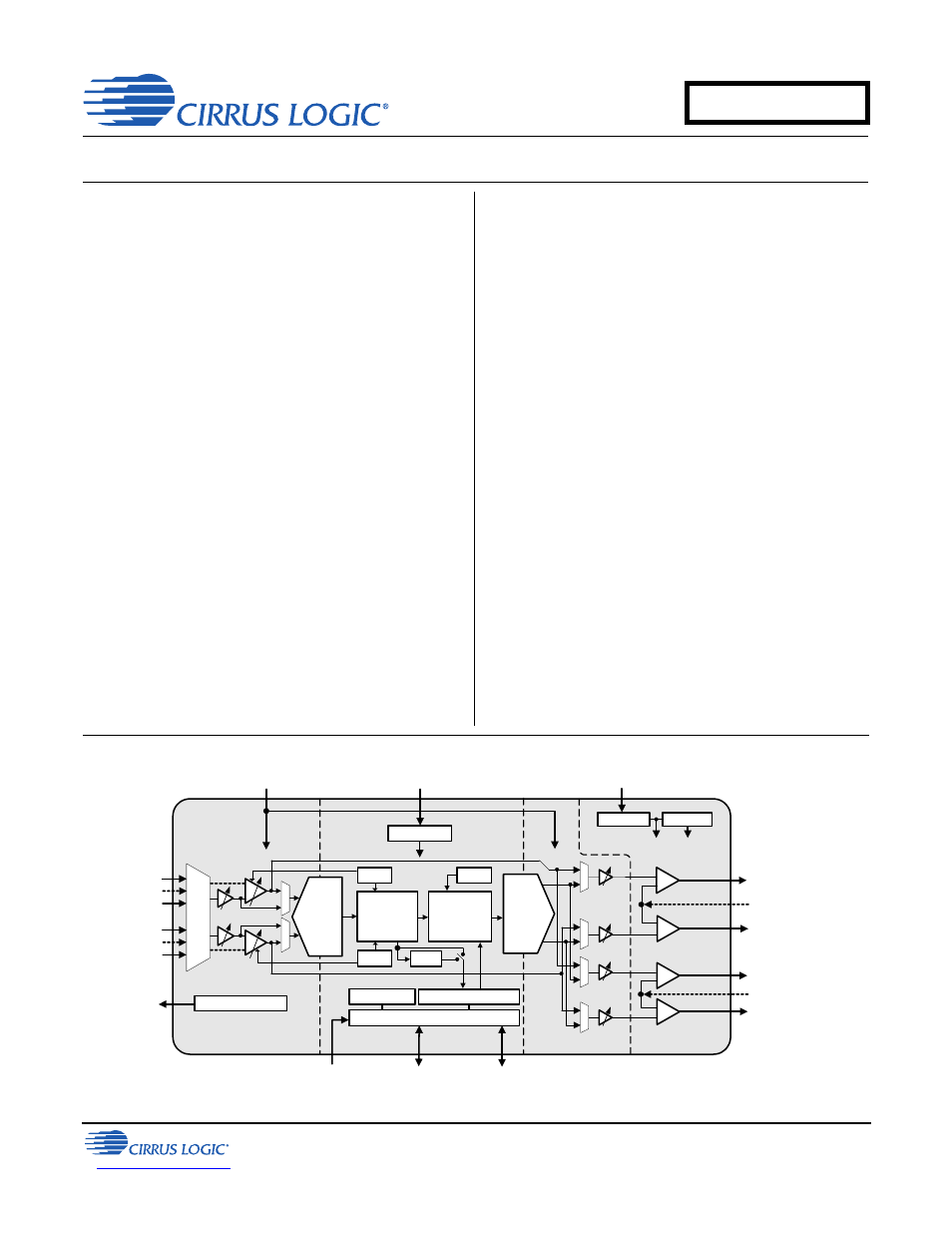
Ultralow Power, Stereo Codec with Class H Headphone Amp
DIGITAL to ANALOG FEATURES
5 mW Stereo Playback Power Consumption
99 dB Dynamic Range (A-wtd)
-86 dB THD+N
Digital Signal Processing Engine
– Bass & Treble Tone Control, De-emphasis
– Master Volume Control (+12 to -102 dB in
0.5 dB steps)
– Soft-ramp & Zero-cross Transitions
– Programmable Peak-detect and Limiter
– Beep Generator with Full Tone Control
Stereo Headphone and Line Amplifiers
Step-down/Inverting Charge Pump
Class H Amplifier - Automatic Supply Adj.
– High Efficiency
– Low EMI
Pseudo-differential Ground-centered Outputs
High HP Power Output at -75 dB THD+N
– 2 x 20 mW Into 16
@ 1.8 V
1 V
RMS
Line Output @ 1.8 V
Analog Vol. Ctl. (+12 to -60 dB in 1 dB steps)
Analog In to Analog Out Passthrough
Pop and Click Suppression
ANALOG to DIGITAL FEATURES
3.5 mW Stereo Record Power Consumption
95 dB Dynamic Range (A-wtd)
-87 dB THD+N
Configurable Analog Inputs
– Two Pseudo-differential Stereo Inputs or
– One Pseudo-differential Stereo Inputs +
One Standard Stereo Input + One Standard
Mono Input or
– Three Standard Stereo Inputs
– Pseudo-differential Inputs Reduce
Common Mode Signal Noise
– 3:1 Stereo Input MUX for ADC or
Passthrough
Analog Programmable Gain Amplifier (PGA)
– +12 to -6 dB in 0.5 dB steps
– +10 dB or +20 dB Additional Gain for
Microphone Inputs
Programmable, Low-noise MIC Bias Output
Programmable Automatic Level Control (ALC)
– Noise Gate for Noise Suppression
– Programmable Threshold &
Attack/Release Rates
Independent ADC Channel Control
High-pass Filter Disable for DC Measurements
HPF
+1.62 V to +3.63 V
Interface Supply
Control Port
Serial Audio Port
Level Shifter
Multi-bit
ADC
Beep
Multi-bit
ADC
ALC
ALC
Multi-bit
DAC
Mono mix,
Limiter, Bass,
Treble Adjust
Attenuator,
Boost, Mix
Left Line Output
Right Line Output
Pseudo Diff. Input
I²S or Left Justified
Serial Audio Input/
Output
I²C or SPI
Control
Digital Supply (VLDO)
+1.62 V to +2.75 V
Analog Supply (VA)
+1.62 V to +2.75 V
LDO Regulator
Inverting
Step-Down
+VHP
-VHP
Charge Pump Supply (VCP)
+1.62 V to +2.75 V
Ground-Centered
Amplifiers
Left Headphone Output
-
+
Right Headphone Output
+
-
+
-
-
+
Programmable Mic Bias
Mic Bias Output
Left Input 1
Pseudo Diff. Input /
Left Input 3
Right Input 1
Left Input 2
Pseudo Diff. Input /
Right Input 3
Right Input 2
0, +10, or
+20 dB
-6 to +12 dB
0.5 dB Steps
Pseudo Diff. Input
CS42L56
Document Outline
- 1. Pin Descriptions
- 2. Typical Connection Diagrams
- 3. Characteristic and Specification Tables
- Recommended Operating Conditions
- Absolute Maximum Ratings
- Analog Input Characteristics
- ADC Digital Filter Characteristics
- HP Output Characteristics
- Line Output Characteristics
- Analog Passthrough Characteristics
- Combined DAC Interpolation & On-Chip Analog FIlter Response
- Switching Specifications - Serial Port
- Switching Specifications - I²C Control Port
- Switching Characteristics - SPI Control Port
- Analog Output Attenuation Characteristics
- DC Characteristics
- Digital Interface Specifications & Characteristics
- Power Consumption - All Supplies = 1.8 V
- Power Consumption - All Supplies = 2.5 V
- 4. Applications
- 4.1 Overview
- 4.2 Analog Inputs
- 4.3 Analog In to Analog Out Passthrough
- 4.4 Analog Outputs
- 4.5 Class H Amplifier
- 4.6 Beep Generator
- 4.7 Limiter
- 4.8 Serial Port Clocking
- 4.9 Digital Interface Format
- 4.10 Initialization
- 4.11 Recommended DAC to HP or Line Power Sequence
- 4.12 Recommended PGA to HP or Line Power Sequence (Analog Passthrough)
- 4.13 Control Port Operation
- 5. Register Quick Reference
- 6. Register Description
- 6.1 Device I.D. Register (Address 01h) (Read Only)
- 6.2 Device Revision Register (Address 02h) (Read Only)
- 6.3 Power Control 1 (Address 03h)
- 6.4 Power Control 2 (Address 04h)
- 6.5 Clocking Control 1 (Address 05h)
- 6.6 Clocking Control 2 (Address 06h)
- 6.7 Serial Format (Address 07h)
- 6.8 Class H Control (Address 08h)
- 6.9 Misc. Control (Address 09h)
- 6.10 Status (Address 0Ah) (Read Only)
- 6.11 Playback Control (Address 0Bh)
- 6.12 DSP Mute Controls (Address 0Ch)
- 6.13 ADCx Mixer Volume: ADCA (Address 0Dh) & ADCB (Address 0Eh)
- 6.14 PCMx Mixer Volume: PCMA (Address 0Fh) & PCMB (Address 10h)
- 6.15 Analog Input Advisory Volume (Address 11h)
- 6.16 Digital Input Advisory Volume (Address 12h)
- 6.17 Master Volume Control: MSTA (Address 13h) & MSTB (Address 14h)
- 6.18 Beep Frequency & On Time (Address 15h)
- 6.19 Beep Volume & Off Time (Address 16h)
- 6.20 Beep & Tone Configuration (Address 17h)
- 6.21 Tone Control (Address 18h)
- 6.22 ADC & PCM Channel Mixer (Address 19h)
- 6.23 AIN Reference Configuration, ADC MUX (Address 1Ah)
- 6.24 HPF Control (Address 1Bh)
- 6.25 Misc. ADC Control (Address 1Ch)
- 6.26 Gain & Bias Control (Address 1Dh)
- 6.27 PGA x MUX, Volume: PGA A (Address 1Eh) & PGA B (Address 1Fh)
- 6.28 ADCx Attenuator Control: ADCAATT (Address 20h) & ADCBATT (Address 21h)
- 6.29 ALC Enable & Attack Rate (Address 22h)
- 6.30 ALC Release Rate (Address 23h)
- 6.31 ALC Threshold (Address 24h)
- 6.32 Noise Gate Control (Address 25h)
- 6.33 ALC and Limiter Soft Ramp, Zero Cross Disables (Address 26h)
- 6.34 Automute, Line & HP MUX (Address 27h)
- 6.35 Headphone Volume Control: HPA (Address 28h) & HPB (Address 29h)
- 6.36 Line Volume Control: LINEA (Address 2Ah) & LINEB (Address 2Bh)
- 6.37 Limiter Min/Max Thresholds (Address 2Ch)
- 6.38 Limiter Control, Release Rate (Address 2Dh)
- 6.39 Limiter Attack Rate (Address 2Eh)
- 7. PCB Layout Considerations
- 8. Analog Volume Non-Linearity (DNL & INL)
- 9. ADC & DAC Digital Filters
- 10. Parameter Definitions
- 11. Package Dimensions
- 12. Ordering Information
- 13. References
- 14. Revision History